3 AG Structures and Concepts
This chapter describes the structure and concepts specific to the Annotation and Graphing (AG) Kit.
- Relationships Between AG objects
- Parameter Values
- Parameters Without Default Values
- Parameters that Determine World Coordinate Limits
- Parameter Types
3.1 Relationships Between AG objects
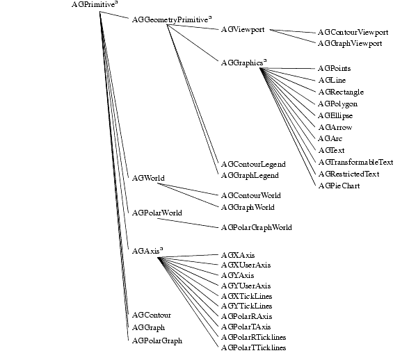
Chapter 1 contains a summary of all the objects in the AG Kit that you can select from the Annotation and Graphing page in the Network Editor. The following figure shows the structural relationship between the group objects, depicted by an inheritance tree. A superscripted "a" denotes internal objects that you should not instance.
The inheritance tree does not relate to how instanced objects can connect to each other. For example, the AGPrimitive group contains the two parameters named priority and visibility, and consequently all the derived objects have these two parameters.
See also the on-line reference page for AGPrimitive.
The AGGeometryPrimitive adds the geometry parameter, and the virtual render and pick methods. Therefore, any object derived from AGGeometryPrimitive can be transformed and rendered directly, by connecting to the AGDataObject that connects directly to a 2D camera (for example, Viewer2D). Note that AGDataObj is not in the inheritance tree because it is a special version of the Graphics Display Kit's DataObject.
See also the on-line reference pages for AGGeometryPrimitive/AGRenderPrimitive and AGDataObject.
Macros That Include Data Objects
As mentioned, you can connect any object derived from AGGeometryPrimitive directly to an AGDataObject and then to a 2D camera (as exists in a 2D viewer). Since this is often the way you use these objects, the AG Kit provides macros that include an embedded AGDataObject. For example, the AGViewportObj is a simple macro combining an AGViewport with an AGDataObject.
AGDataObject is almost identical to the DataObject module in the Graphics Display Kit, except AGDataObject only allows objects derived from AGGeometryPrimitive to connect to it. Just like the DataObject, AGDataObject can connect to a GroupObject (also from the Graphics Display Kit).
Please note that the AGDataObject contains the transformation matrix, so you can only transform objects connected to an AGDataObject using the mouse for scaling, rotating, and translating.
Possible Connections
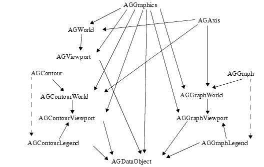
The following figure pictorially describes possible connections between the different objects in the AG Kit.
The following list describes the rules regarding the possible object connections.
- Every object derived from AGGraphics can connect to any World, any Viewport, or directly to the AGDataObject.
- Every object derived from AGAxis can connect to any World object.
- AGGraph and AGContour connect to AGGraphLegend and AGContourLegend, respectively, to give information to the Legend.
- AGGraph and AGContour connect to AGGraphWorld and AGContourWorld, respectively.
- Any AGWorld connects to a Viewport of the same type (for example, AGGraphWorld connects to an AGGraphViewport).
- Any AGViewport connects directly to an AGDataObject.
- AGWorld objects will accept multiple AGPrimitive objects as input, or they will accept a single input that is an array of type AGPrimitive. For example, you could connect an AGLine, AGText and AGGraph object as input to AGGraphWorld. Or, you could connect a single AGText array (something declared as AGText foo[10], for example). However, if you want to connect both the array and 1 or more AGPrimitive objects, you must use the AGCombineGraphWorldInput or AGCombineContourWorldInput objects.
The Network Editor guides you in connecting ports by only showing valid possible connections. Additionally, the ports of AG objects are color-coded to show which connections are possible. The input and output port colors in the AG Kit have the following meanings:
The Purpose of the Connections
The connections between the objects serve two functions in the AG Kit. When something is changed in an object, all its children are notified and can behave accordingly by performing a redraw. Connections are also used for retrieving parameter values in the case when an unset parameter is encountered. Please refer to the next section about parameters for more information on this.
3.2 Parameter Values
Whenever an object needs the value of a parameter at draw time (for example, an AGXAxis needs the axleColor parameter), the following occurs:
- If the value is set, it is used as is.
- If the value is unset, the connected parent is asked for the parameter and if the parameter is set that value is used. If the parent's value is also unset, the parent's parent is asked, and so on.
- If a set value is not found anywhere above in the connection hierarchy, an internal default value is used.
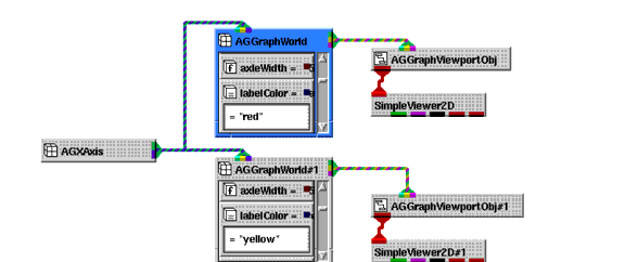
A given object can easily have connections to two or more parents. For example, an AGGraphWorld can be the parent of an AGXAxis. If an AGXAxis connects to two AGGraphWorld's that each connect to an AGViewportObj then a Viewer, the AGXAxis is drawn twice-once for each AGGraphWorld. Consequently, if the labelColor parameter is unset in the AGXAxis and set to different values in the two AGGraphWorld's, the axis is drawn using different colors for the labels depending on the current connection path at draw time.
3.3 Parameters Without Default Values
Some parameter's default values are based on the value of other parameters. For example, the isoLineLabelDecimals parameter controls the default number of decimals on isoline labels. When unset, the default value is based on the range of the data. If the data ranges from 0.01 to 0.1, a value of 3 is used for the number of decimals shown on isoline labels; whereas, if the data ranges from 10 to 100, a value of 0 is used.
3.4 Parameters that Determine World Coordinate Limits
The parameters that determine the world coordinate limits are limitsX and limitsY in the AGWorld object. If the world coordinate limits in one of the AGWorld object types is unset, which is the default value, the limits are calculated based on the rules in the following list. (Please note that the following applies to the limitsX and limitsY parameters independently.)
- The limits of all the children connected to the World are checked, and the minimum and maximum of these values are used.
- If the niceLimits parameter is set, the limits are moved to some nice values. For example, if limitsX of all the children is {0.23, 9.55}, setting niceLimits changes limitsX to {0.0, 10.0}.
- If the uniformScaling parameter is set, the limits are forced to equal distances in the X and Y directions. In this case, the entire AGViewport that contains the AGWorld might not be completely filled.
See also the on-line reference page for AGWorld.
Please note that an AGGraph object that has the valuesX parameter unset has the X limits {0.5, number of Y values + 0.5}.
See also the on-line reference page for AGGraph.
3.5 Parameter Types
The following table lists V type definitions and descriptions for parameters in the AG Kit. Note that enumerated parameters are implemented as strings rather than integers. If an enumerated parameter contains a space (for example, "filled contours"), the space is not displayed when viewing the value in the Module Stack workspace.
Table C-1
"dashed"
"dotted"
"dasheddotted"
(You can also provide a visual representation of these line styles. See Line Style Parameters)
String Parameters
You use the AGString parameter for plotting text. The text can be the text of an AGText object or the title in an AGGraphLegend. The characters in the following list have a special meaning:
Color Parameters
The AGColor parameter accepts X11 color names, "#rrggbb" color format, and three strings with special meaning. When using the "#rrggbb" format, rr, gg, and bb specify a hexadecimal representation of the value for the red, green, blue color component (for example, "#ff0000" is "red"). The AGColor strings having a special meaning are as follows:
- "background" is always black on a screen, but is white on a white paper hardcopy.
- "antibackground" is always white on a screen, but is black on a white paper hardcopy.
- "transparent" makes an object or part of an object transparent (i.e., it is not drawn at all). For example, if the fillColor parameter in an AGPolygon object is set to "transparent", only the outline is drawn and no fill is drawn.
AGColor parameter accepts all the X11 color names. Please note that the names are case insensitive and spaces are ignored (for example, "Light Slate Blue" is identical to "lightslateblue").
Font Parameters
AGFont parameters accept a subset of normal PostScript font names, plus some additional software generated fonts. If a name contains spaces or dashes ("-"), they are ignored (for example, "Roman Italic" is identical to "roman-italic"). Names are not case sensitive.
When a font is prepended with the characters "sw:", the text is software generated text, so it is a series of lines and/or polygons. When a font is prepended with "hw:", the text is hardware generated when possible. Please note that X Window version 11 servers only draw text horizontally, so rotated text is generated by software. The supported font names are as follows:
The on-line reference page on Fonts and Special Characters gives examples of the font styles.
Line Style Parameters
Any AGLineStyle parameter can be set to one of the following strings:
"solid"
"dashed"
"dotted"
"dasheddotted"In addition, in place of one these strings, you can enter a string of periods and underscore characters representing the line style you want to draw. The following table lists the strings you can use. Note that you must use the correct number of characters in the string.
The Priority Parameter
The priority parameter determines the drawing order. Objects having higher priority values are drawn last so that they appear in front of other objects. For example, to move a curve in front of another curve, you assign a higher priority to the former curve. By default, all objects have a priority of 0 and the connection order determines the drawing order.
The priority only has an effect when an object has more than one child object connected to it.
See Setting the Drawing Order Using the Priority Parameter.
The Visibility Parameter
If the visibility parameter is set to 0, the object containing this parameter is not drawn. Setting this does not affect any other objects.