1 Welcome to AVS/Express
- What is AVS/Express?
- Working with AVS/Express
- AVS/Express Kits
- Object-oriented Techniques in AVS/Express
- Connections and Object Execution
- Object Manager
- Developing and Delivering Applications
AVS/Express is an object-oriented, visual development tool that enables you to build reusable objects, application components, and sophisticated data visualization applications.
- Object Oriented - AVS/Express' development approach is object-oriented; it supports the encapsulation of data and methods; class inheritance; templates and instances; object hierarchies; and polymorphism. In AVS/Express, all application components, from the lowest to the highest level, are objects.
- Note: The terms application component and object are used interchangeably in this book and in other AVS/Express documentation.
- Visual development - The Network Editor is AVS/Express' main interface. It is a visual development environment that is used to connect, define, assemble, and manipulate objects through mouse-driven operations.
- Visualization application - AVS/Express provides hundreds of predefined application components (objects) that process, display, and manipulate data. The objects and application components that you connect and assemble in the Network Editor control how data is processed and how it is displayed. If you choose, you can compile and package those objects and even add a user interface to create a complete application that can be delivered as a stand-alone application.
AVS/Express offers several ways to use objects. You can:
- embed them in AVS/Express applications
- execute and control them in server mode from an external C or C++ routine
- create components that represent standalone applications
AVS/Express also provides full support for integrating C, Fortran, and C++ code. Components can perform their processing by calling a C, Fortran, or C++ routine. You can also use code template generators to import user-written code and data with little modification. Similarly, the C++ class generator enables you to use the power of C++ programming to access AVS/Express components.
There are three aspects of AVS/Express that can be used to create an visualization application. You can use any combination of the main interface (the Network Editor), the AVS/Express V programming language and the V code processor (VCP), or you can use the AVS/Express application programmer interfaces (APIs).
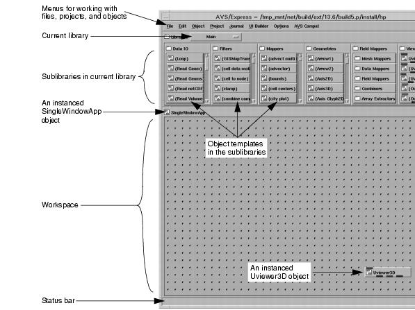
Your primary development tool is the Network Editor. The top section of the Network Editor consists of libraries of objects. The bottom section is the workspace where you drag and drop objects and draw connection lines between objects (connection lines indicate data references) to assemble an application or to create new objects.
- Note: This manual sometimes uses a white background for the application workspace. The background you will see when you start AVS/Express is a pegboard.
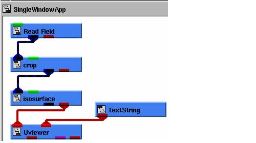
The graphic below demonstrates the simplicity of a complete data-visualization application as it appears in the application workspace.
By using only five objects (Read Field, crop, isosurface, Uviewer, TextString) and four connection lines, this application:
- reads a field data file (Read Field object)
- processes the data (crop and isosurface)
- displays the results in a full-featured data viewer (UViewer)
The Network Editor provides access to all AVS/Express objects, subobjects, and parameters; however, you can also view, add, delete, or edit objects by manually editing the underlying code for the objects. The code for AVS/Express objects is called V code.
You can access and use V code in several ways:
- You can use a text editor to create a V file that defines a set of objects, and then you can read that V file into AVS/Express.
- You can use the Network Editor to save objects into a V file. If you choose, you can edit the V file to modify the objects, or you can leave the file in its original state and then read the V file back into AVS/Express.
- While working with AVS/Express, you can interactively enter V statements and commands through the V Command Processor (VCP). The VCP is particularly useful for examining and debugging applications.
AVS/Express allows you to integrate user code into an application via application programmer interfaces (APIs). You can do this in two ways:
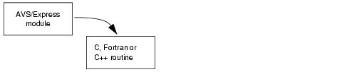
- Call a routine from an object - An AVS/Express object can call a C, Fortran, or C++ routine to perform its processing. In AVS/Express, an object that takes input data, performs processing, and produces output data is called a module.
- Manipulate instances of objects - A C, Fortran, or C++ routine can create, destroy, and modify instances of existing AVS/Express objects. This allows you to build an application that calls AVS/Express in server mode to carry out some aspect of the application, such as visualizing a set of data.
AVS/Express has several tools to help you integrate user code. For example, you can use AVS/Express' C++ class generator to generate a C++ class that controls an AVS/Express object.
Component technology is the ability to create an application from reusable, modular pieces, or components. AVS/Express offers component technology through its wide assortment of predefined application components. You can also use AVS/Express to create your own components or you can use components developed by other AVS/Express users.
AVS/Express organizes its predefined components into libraries. AVS/Express offers the following libraries:
- Data Visualization - The data visualization objects enable you to read, manipulate, transform, and analyze multi-dimensional, multi-variate data. In addition to its many modules, the Data Visualization Kit includes an API for creating new visualization objects. Most data visualization objects are prefixed with "dv."
- Image Processing - The image processing objects enable you to read multi-banded image data and perform over 40 image processing functions (for example, blend, edge, dilate, and fft). Most image processing objects are prefixed with "ip."
- Graphics Display - The graphics display objects enable you to build interactive 2D and 3D graphics-display applications. The Graphics Display Kit offers pre-built data viewers that you can use out-of-the-box or customize. Most graphics display objects are prefixed with "gd."
- Annotation and Graphing - The annotation and graphing objects enable you to build sophisticated graphs of multi-dimensional data. Annotation and graphing objects include titles, arrows, circles, charts (for example, bar, pie, staircase), legends, and axes. Most annotation and graphing objects are prefixed with "ag."
- Database - The database objects enable you to access and modify the data in a local or remote relational database from an AVS/Express application. Most database objects are prefixed with "db."
- User Interface - The user interface objects enable you to build platform-independent graphical user interfaces. User interface objects define windows, dialogs, widgets, interactors, and render views. AVS/Express' Layout Editor lets you modify user interfaces through direct manipulation. Most user interface objects are prefixed with "ui".
- AVS5 Compatibility - The objects in the AVS5 compatibility library enable previous users of AVS5 to use existing AVS5 modules.
AVS/Express supports many object-oriented techniques: the encapsulation of data and methods; inheritance; templates and instances; object hierarchies; derivation hierarchies, and polymorphism. Below is a very brief overview of how these techniques are used in AVS/Express. For a detailed explanation, refer to the Using AVS/Express.
- Encapsulation of data and methods - Objects encapsulate (or bind together) both data and the methods that operate on the data. The major advantage of encapsulation is that a single entity can represent everything associated with a particular object. This provides the basis for component engineering, where newly developed components can be dropped into existing applications.
- inheritance - An object can inherit the characteristics of one or more other objects. This is called subclassing. If you create an object from another object, the new object acquires both data and methods from the original object. The new object can modify its inherited data; similarly, the new object can define additional data and methods. The major advantage of inheritance is that you can define a set of data and methods once, but have those characteristics inherited by many objects.
- Templates and instances - AVS/Express objects are referred to differently depending on where those objects exist. If you are looking in the AVS/Express libraries, the objects are considered templates; they contain the definition of the object. If you drag an object's icon from the library into the workspace, the template remains in the library, but what appears in the workspace is an executable instance of that object.
- Note: The fact that the object's template remains in the library means that you can create multiple instances of the same object.
- Object hierarchies - AVS/Express allows you to combine objects to form higher and higher-level objects. Most objects you see in AVS/Express are actually collections of other objects. By opening an object, you can view and modify its underlying definition.
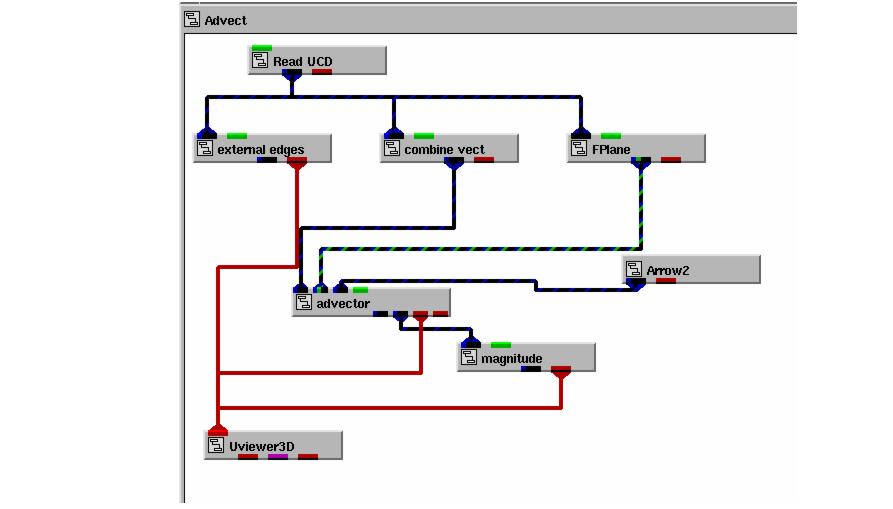
- For example, Advect is a module that contains an example application. You can find it in the Visualization sublibrary of the Examples library. Here is what Advect looks like in the Network Editor:
- By instancing and double-clicking on Advect, you can maximize it to view its constituent objects:
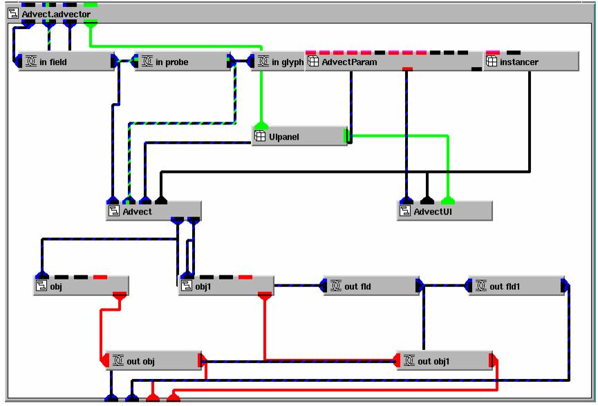
- As you can see, Advect is actually a collection of other objects, named Read UCD, advector, Arrow2, and so forth. Many of these objects are themselves collections of objects. You can continue to open objects within objects and "drill down" into the object hierarchy in order to change or add lower-level objects. For example, if a you double-click on advector in the network above, it too maximizes to show its sub-objects:
- Polymorphism - Polymorphism literally means many forms. In AVS/Express, it means that an object can operate on different types of data, and work differently depending on the data it receives.
- For example, the isosurface object can accept either 2D or 3D data. If you pass a 2D data set into isosurface, it creates isolines. If you pass it a 3D data set, it creates an isosurface.
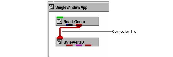
An AVS/Express object can reference another object's data. You do this by connecting the port of one object to a port of another object. For example, the application below shows a connection line between the red ports on the Read Geom object and the Uviewer3D object.
The Read Geom object reads a data file and creates an AVS/Express field and the Uviewer3D object provides a full-featured data viewer. The connection line between the two objects specifies that Uviewer3D should display the data created by Read Geom. Uviewer3D does not copy Read Geom's data; instead, it references the data.
In AVS/Express, connections not only define how an object gets its data, the connections also drive the execution of the application. When data changes, objects that reference the data are notified of the change, and this typically causes the object to execute.
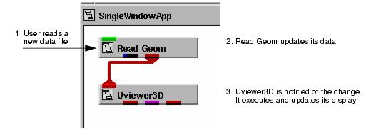
For example, consider the data visualization application consisting of Read Geom connected to Uviewer3D. If the developer of this application decides to read a new data file, the act of reading a new data file causes Read Geom's data to change. Because Uviewer3D is connected to Read Geom, it is notified of the change, and this notification causes Uviewer3D to execute and render the new data.
In AVS/Express, order of execution is not determined by a set of procedural instructions or message-passing schemes that you would otherwise need to code, instead it is controlled by the connections that you make among the application's objects.
When necessary, you can explicitly control execution. For example, in cases where order of execution is important but ambiguous, you can indicate object dependencies to control execution. You can also use a C, Fortran, or C++ routine to explicitly set notifications on objects to force their execution.
At the heart of AVS/Express is a powerful runtime engine called the Object Manager. You do not see it, but the Object Manager manages the definition and execution of your application.
- validates objects as you build them
- executes objects
- manages an object's data
- manages the connections between objects and schedules their execution
- invokes an object's methods
- handles API calls from C or C++ routines to update objects and their data
- supports multi-process computing, whereby objects can be moved from process-to-process without modification
- This provides a convenient debugging environment for isolating fault-prone or rapidly changing code as it is developed.
In general, the AVS/Express Object Manager makes no assumptions about the data it manages. However, to provide the optimized set of visualization tools included in the Data Visualization Kit a set of visualization-specific data structures are defined. These structures are collectively known as a field.
To build an application using the facilities of the Data Visualization kit, it is important to understand the field data structure. One of your first tasks will be to decide how to represent your data using AVS/Express fields.
A field can consist of four main components:
- The grid defines a set of nodes and their locations in the data space.
- For some types of fields, you define the locations by providing the coordinates of each node. For field types that have more structure you can provide less information. For example, you can specify the location of the axes instead of every point.
A cell set contains a node connectivity list, which is a list of indices into a field's array of node coordinates that describes how to connect the nodes. The cell set's type determines the shapes that are generated when the nodes are connected. For example, consider a cell set that describes a series of triangles. The first three elements in the node connectivity list indicate the indices of the coordinates that define the first triangle in the cell set. The second three elements indicate the indices of the coordinates that define the second triangle, and so forth.
The grid and cells together make up a mesh.
- Node data is data that you can provide for each node. Node data is optional, not all fields will have node data.
- The node data is usually mapped to a color in the rendered visualization, so that changes in the data values correspond to changes in color.
Cell data is associated with the group of nodes that make up each cell. Cell data is optional, not all fields will have cell data. AVS/Express can use this data when rendering the surface of the grid, or to interpolate to the node data.
Node data and cell data make up the data.
The data components (node data and cell data) are optional and you do not always need to explicitly provide cells.
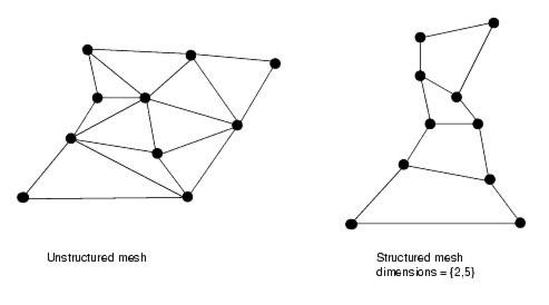
In AVS/Express, a mesh is formed by a grid and a cell. There are two basic types of meshes, structured and unstructured. Structured meshes have dimensions. The dimensions of a mesh are the number of nodes along each axis of the grid. Structured meshes have an implied connectivity. Unstructured meshes do not have dimension and require that you explicitly provide the connectivity.
The diagram below shows an unstructured and a structured mesh. Neither mesh looks particularly organized or structured, but there is an important distinction between the two. You can not specify the dimensions for an unstructured mesh; but you can specify the dimensions for a structured mesh.
Below is a diagram of a structured mesh. The columns and rows form a 2 dimensional mesh. This diagram shows a structured mesh of dimensions 3x6.
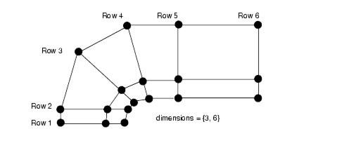
- Note: In order to obtain this shape, the coordinates had to be specified in the proper order. The first three coordinates specify the locations of the nodes in row 1, left to right. The second three coordinates specify the locations of the nodes in row 2, and so forth.
Under the classification of structured mesh are two subclasses. These are Uniform and Rectilinear.
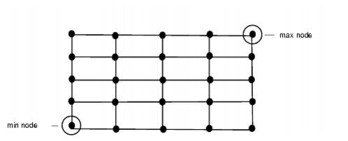
The uniform mesh is the most structured of the structured mesh types. In this type of mesh, the spacing of the nodes along each axis is uniform. The distance between two nodes along a given axis is the same. Because these is so much regularity in the spacing of the nodes in a uniform mesh AVS/Express can compute much of the grid information. You only need to specify only the coordinates of the minimum and the maximum nodes in a data set. Given those two nodes and the data set's dimensions, AVS/Express can compute the location of all other nodes. Below is an example of a 2 dimensional uniform mesh.
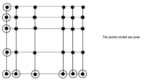
A rectilinear mesh is one where you specify only the nodes along the axes. The nodes need not be uniformly spaced. The location of all other non-axis nodes are computed by AVS/Express and are located at the intersection of the lines passing through the axis nodes. The mesh pictured below is a simple 2 dimensional rectilinear mesh.
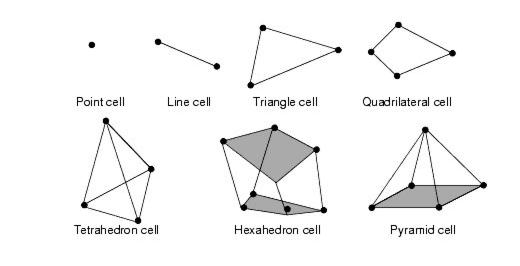
In an unstructured mesh you must explicitly define how the nodes are organized by using cell sets. Cell sets provide information on how the nodes and data are connected to each other. Each cell set needs to include the following information
- The cell type, for example, tri, quad, polytri and so on. (see diagram below)
- The number of cells that are in the cell set
- A connection list that specifies how the nodes you provided in the field's grid connect to form the cells.
When you work with AVS/Express, your goal is typically to create a data visualization application. The application could be for only your use, it could be something that will be used by other people in your company, or it could be something that will be compiled, productized, and sold to other customers. What you deliver to the customer, whoever that customer might be, is an application. In AVS/Express terminology, what you work on while you are developing the application is called a project.
An AVS/Express project defines your development and execution environment. A project includes:
- Libraries - the libraries of template objects
- External code - C, Fortran, or C++ routines
- Processes - the express executable, as well as any external processes
When you start AVS/Express, you access AVS/Express' development and execution environment, in other words, you start and access a default project. When you save your application, you save all of the objects that make up that application as well as the environment (libraries, code, and processes) that supports that application. In AVS/Express terminology, this means that you save a project for your application. The project that you save defines itself as being like the install project with any additions and changes you make.
Once you have created a project, you can define chains of projects, whereby a project is a derivative of some other project, which in turn is a derivative of yet another project. This allows a group of developers to share objects and work on specific objects that are unique to their own development tasks.
You can use AVS/Express in three ways to deliver complete applications as well as smaller application components.
- You can use AVS/Express to build, debug, and deliver complete applications that can be run in any version of AVS/Express. You can also generate run-times of those applications and deliver them as standalone executables.
- You can build reusable application components that can be embedded in other applications or called from outside AVS/Express.
- AVS/Express can be used as a server under the control of a client program. The client either starts AVS/Express or connects to an already executing instance of AVS/Express. Through an API, the client then instances and executes AVS/Express objects.