

 |

 |
Crop a 3D region (RegionCrop3D)
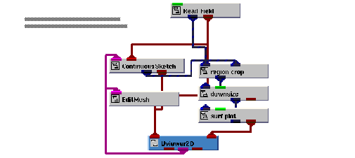
Another example that involves some of the interactive 2D drawing modules is to select a region within an image in a 2D view using the ContinuousSketch module. The selected region is then displayed as a surface in a 3D view.

Instance RegionCrop3D into the empty NE workspace.
This example is found in Libraries.Examples.Graphics_Display. The example renders the image of Mount St. Helens in the 2D viewer's window. The image appears normalized in the view. The 3D view has nothing rendered in it initially.
Select a region from the image
We are now ready to select a region in the image to be displayed as a surface in the 3D view.
Select Editors->Modules to make the modules user interface panel visible. Select ContinuousSketch from the Modules option menu. This causes the user interface for the ContinuousSketch module to appear.
Begin drawing a box, using the draw primitive operation.
The mouse operations that control the drawing in the ContinuousSketch module are:
|
|
|
In this example, the ContinuousSketch module is set up to draw a box in XOR mode. Once the operation is complete (that is, the right mouse button is released), the box is converted into a field since the Immediate toggle is set.
The extents of this field are used as input parameters by the region crop module to select the region to display in the 3D view. Note that region crop is a macro that was built for this example. The V code for it can be found in v/gd_examp/GDinter5.v .
This touches on only a small portion of the capabilities in the ContinuousSketch module.
View the region in the 3D view
Once a region is selected in the image, you can also view it as a surface in the 3D view.
Look at the selected region in the 3D view.
A completely new region can be selected by repeating the same process that was used to generate the initial region.
Alternatively, we can edit the region in the 2D view and observe the effect that it has on the surface in the 3D view.
Select EditMesh from the Modules option menu. This causes the user interface for the EditMesh module to appear in the ModuleStack window.
In this example, the EditMesh is set up to edit a cell.
Edit the drawing by performing a select/move primitive operation.
The mouse operations that control editing in the EditMesh module are:
|
|
|
|
Press Control left button while the mouse is over a point or line in the drawing. | |
|
Hold down the Control key and drag the primitive while depressing the middle button. |
When the select operation takes place, the region is drawn in the highlight color.
When the move primitive operation is in progress, the current position of the updated region is echoed in the highlight color. By default, the EditMesh module is configured so when the move primitive operation is completed, the field is updated. This causes a new region to be cropped from the image and rendered in the 3D view as a surface.
Delete the RegionCrop3D application.
 |

 |