7
Using the Data Viewers
The chapter provides detailed reference information on the DataViewer editors. AVS/Express makes these editors available by default in the SingleWindowApp and MultiWindowApp start-up applications. They are included in the Uviewer series of viewers. You can use these editors to control the rendering and display of your visualization.
- Using the View Editor7-2
- Using the Transform Editor7-12
- Using the Light Editor7-19
- Using the View Object Editor7-27
- Using the Camera Editor7-53
- Using The Datamap Editor7-66
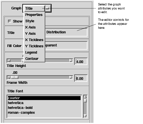
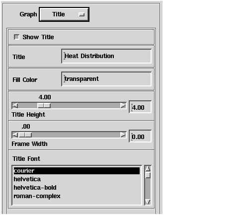
- Using the Graph Editor7-79
You can use the View editor to control the display characteristics of the Dataviewer display window, and to add additional scenes to the DataViewer application. When it is first opened, the View Editor looks like this:
You can select the following options from the View option menu:
Table G-1
controlling the image display including the use of a frame buffer and z buffer.
The remainder of this section discusses the View Editor tasks.
You can use the Renderer option menu to select a renderer.: The selected renderer will be used to draw the scene for the current camera. You can choose from the following options:
- Choose Software to use a software renderer that implements its own graphics rendering techniques in software, outputting an X image
- Choose one of the hardware renderers (OpenGL, XGL, PEX, or XIL) to use your workstation platform's underlying software and hardware graphics facilities to produce the screen rendering
Renderers that are not available on your platform are grayed out in the Renderer option menu.
If your platform includes a hardware renderer, it is used as the default. Otherwise, the default is the software renderer. If your platform does not support hardware rendering facilities, only the software renderer editor options will be available.
For detailed information about the platforms and features supported by the hardware renders, see the section on Rendering Across Platforms in the Installing AVS/Express manual.
Click the Refresh bar to force the display to be redrawn. A refresh updates any changes in the data or display characteristics.
By default, the DataViewer automatically updates the display whenever the view changes, for example if you transform an object or the data changes. You can use the Update Automatically toggle on the View editor Options panel to turn off the automatic update.
For information about the Update Automatically toggle, see Enabling and Disabling View Options on page 7-5.
You can use the Width and Height text fields to change the width and height, in pixels, of the viewer window. The default value of each is 500 pixels.
If you change the dimensions of the display window in the Single-window DataViewer application, the entire window, including the editors panel, resizes to frame the new dimensions. However, reducing the height to less than 500 pixels may cause some of the editor panel controls to be cut off.
You can use the Background Color Editor to change the color of the background in the viewer window:
You can adjust the Hue, Saturation, and Value dials to specify the hue, saturation and brightness parameters, respectively, of an HSV color space that defines the background color of the Viewer window. An HSV color space can be thought of as an inverted cone:
- The hue axis runs circularly around the cone. Here are some examples of hue values and the corresponding hues:
- The saturation axis runs from the center of the cone (white) to its perimeter (fully saturated color). Here are some examples of saturation values and the corresponding saturation levels:
- The brightness axis runs from the tip of the cone (black) to the base (white). Here are some examples of brightness values and the corresponding brightness levels:
For the Viewer window background color, the default settings for hue, saturation, and brightness are 0.00, and the background appears black.
By default, the background color is applied the next time the view is refreshed. Use the Immediate button to apply the color immediately.
You can choose the View editor Options command to control a set of basic display options:
You use this interface to enable and disable double buffering, the timer, and automatic updates.
You can use the Double Buffer option menu to enable or disable double buffering:
- Choose Single to enable single buffering. The view is drawn directly to the screen.
- Choose Double (MBX) to enable double buffering using the X11 MBX extensions.
- Choose Double (Pixmap) to support double buffering by rendering into a pixmap that is then copied to the view.
By default, the view is double-buffered. If you use a software renderer, the default double-buffering is the pixmap method.
- Note: On the Windows version of AVS/Express, only Single and Double options are available.
- Note: The two different double buffer modes (MBX or Pixmap) are only valid for the software renderer. For the hardware renderers - OpenGL, XGL, PEX or XIL - setting either MBX or Pixmap enables hardware double-buffering.
In the software renderer, 2D cameras can be rendered using any buffer mode. However, 3D cameras in the software renderer are always double buffered since the objects in them are rendered to an off-screen frame buffer and then converted and copied to the screen.
You can use the Timer to get a measure of the display performance of your system to compare the performance of different system configurations or graphics adapters. The Timer calculates the frames per second generated by the display while transforming a 3D object and displays the results on the View editor panel.
3. "Throw" the object by pointing your cursor in the viewer window, holding down the left mouse button, and moving the cursor quickly across the window.
AVS/Express prints the total time, total number of frames generated, and the number of frames per second in the AVS/Express console window.
You can use the Update Automatically toggle to control when the viewer window display is updated. By default, Update Automatically is on, and the DataViewer automatically updates the display whenever the view changes, for example if you transform an object or the data changes.
If you turn Update Automatically off, the view is not updated. The DataViewer queues changes until you turn Update Automatically on or Click the Refresh bar on the Option editor General panel to force the display to be redrawn.
If you turn the Accelerate option on, AVS/Express attempts to speed up rendering by storing the image of static objects. When dynamic objects are changed, AVS/Express can rendered them into buffers already containing the rendered static objects - the static objects need not be re-rendered unless they are also changed. Accelerate mode can be useful if you are moving simple objects around a complex scene, for example, moving symbols around a complex map.
You can control which objects are static or dynamic by setting the Dynamic toggle on the Object editor General panel.
- Note: The performance you get from Accelerate mode can vary greatly depending on the buffering techniques used by the renderers on your platform. In some configurations Accelerate may not offer significant advantages. Be sure to test for performance improvements in your environment.
For more information about measuring the display performance of your system, see Using the Timer to Measure Performance on page 7-7
If you are using the XGL renderer on SunOS 5 systems, you can turn Pcache on to enable pcaching. Pcaching renders using a form of display list processing. For some graphics adapters, this can result in significantly improved performance. However, this method also uses more memory and is not generally recommended. Be sure to test for performance improvements in your environment.
For more information about measuring the display performance of your system, see Using the Timer to Measure Performance on page 7-7
You can use the Output panel of the View editor, to control output from this view:
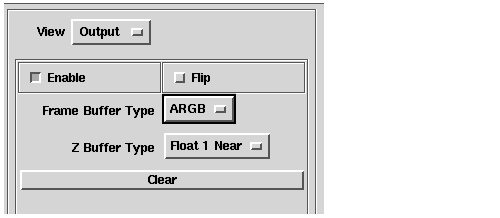
Turn Enable on to enable output from this view. When you enable output,
Turn Flip on to invert the contents of the view before writing it to the buffers.
Click the Clear bar to clear the output buffers of all previously stored primitives.
You use the Frame Buffer Type options to specify the format that AVS/Express uses to store the image in the frame buffer. The letters in each option describe the order in which the alpha (A), red (R), green (G), and blue (B) data components are stored.
For best performance, choose the format based on the type of renderer you are using:
- None - No framebuffer output.
- ARGB - Framebuffer output is in ARGB order. Use this format with the software and PEX renderers.
- This is also a "canonical" format that is used by all the renderers. Use this format if you want to exchange framebuffer information between renderers.
- RGBA - Framebuffer output is in RGBA order. Use this format with the OpenGL renderer.
- ABGR - Framebuffer output is in ABGR order. Use this format with the XGL renderer.
You use the Z Buffer Type options to specify the format that AVS/Express uses to store Z-buffer data.
For best performance, choose the format based on the type of render you are using:
- None - No Z-buffer output.
- Short - Z buffer output is unsigned short values in the range 0-65534 with 65534 nearest the viewer. Use this format with software rendering.
- Float 1 Near - Z buffer output is float values in the range 0-1 with 1 nearest the viewer. This is a "canonical" format that is accepted by all the renderers. Use this format with any of the renderers not mentioned specifically here, or if you want to exchange Z-buffer information between renderers.
- Float 0 Near - Z buffer output is float values in the range 0-1 with 0 nearest the viewer. Use this format with OpenGL renderers.
- Int - Z buffer output is int values with 0 nearest the viewer. Use this format with XGL renderers.
You can use the Create panel of the View editor to add a scene to the DataViewer application:
You can use the New Camera Type options to create the new view with a 2D camera, a 3D camera, or both.
You can use the Object Mode options to choose to create the view for New objects or for the Same objects:
- New Objects - When you create a view in the New Objects mode, AVS/Express creates an empty view and adds input ports for the cameras you have specified to the Uviewer in the Network Editor. For example, here is the Uviewer in the example application after adding a view with both 2D and 3D cameras:
- Same objects - When you create a new view in the Same objects mode, AVS/Express creates a separate view that displays the same objects as the current view. These are not copies of the original objects, but a new view on the same objects. If you transform or otherwise edit the objects, the changes appear in both views. The views also share the same lights and datamap.
- However, you can edit the view and camera separately for each view. This allows you to create views of the same objects with different viewpoints or rendering characteristics.
- If you have a current view using both the 2D and 3Dcameras, and you create a new view with only one camera but with the same objects, the new view includes only the objects in that were in the type of camera you selected. The objects in the other camera are not included in the new view.
Click the Create View bar to create the view you have specified. AVS/Express adds a choice representing the view to the Windows menu in the DataViewer menu bar. The first scene you add is given the name View#1. If you add additional views they will be numbered sequentially.
When you add a view to the SingleWindow application, the view is created in the view window and appears in place of the display of the current view. You can page the different views to the front of the window by selecting them from the Windows menu in the menu bar. You can only edit the currently selected view.
When you add a view to the MultiWindow application, the view is created in another separate viewer window. Each window may be moved and displayed separately. To edit a view, select it by clicking in the window viewer space.
The Transformation Editor is an interactive tool with which you modify how a transformation is performed on a selected object.
When you select Transform from the Editors menu, AVS/Express displays the following editor panel:
You can transform objects in the DataViewer view window interactively by using your mouse in the window, or you can specify a transform by setting explicit values. The Transform editor options support both methods:
- Select Interactor Behavior to control how mouse interactions in the viewer window transform the selected object.
- Select Transform to display a set of controls that you can use to transform the selected object by setting explicit values, instead of using the mouse.
The transformation performed depends on two other settings in the DataViewer:
- The transform object selected. You can choose to transform the current view object, camera, or light.
- The transform mode selected. You can choose four different types of transforms: rotate, scale, XY-translate, or Z translate.
You select which type of object to transform by choosing the appropriate icon from the DataViewer toolbar:
You can perform four different types of transforms with the mouse. You specify a transform mode to determine which type of transform the left mouse button performs on the selected object. To set the current transformation mode, click on the appropriate icon in the viewer window tool bar:
- The left mouse button rotates the selected object.
- The left mouse button scales the selected object.
- The left mouse button moves the selected object in the XY plane.
- The left mouse button moves the selected object in the Z direction.
Selecting the Interactor Behavior option on the Transform editor provides the following user interface:
You use this dialog box to control how your mouse interactions are interpreted in the viewer window.
You can use the Local Space toggle to transform the object in its local coordinate system rather than the global coordinate system.
By default, objects are transformed in global space. When you rotate an object, for example, you are rotating the entire coordinate system of the Top view. If you then want to rotate an object locally, around its own axes, set the Local Space toggle on.
If you turn Local Space on, the objects are transformed in their local coordinate system.
By default, the scaling operation in the viewer window is uniform. When you click the scale icon in the viewer window toolbar, dragging your mouse in the viewer window scales the object equally in all dimensions. Dragging the cursor up or to the right makes the object appear larger; dragging the cursor down or to the left makes it appear smaller.
When you turn Non_Uniform Scaling on, you can scale the dimensions of the view independently. Moving the cursor up and down scales the height of the object in the current view: moving the cursor up increases the height, moving it down decreases it. Moving the cursor left and right scales the width of the object in the current view: moving the cursor to the left decreases the width, moving it right increases it.
You can use the Rotation Mode options to control how AVS/Express interprets mouse interactions in the viewer window in rotation mode. You enable rotation by clicking on the rotate icon in the viewer window tool bar.
You can choose from the following options:
- Arbitrary - Allow arbitrary rotation.
- XY - Constrain rotation to the XY axis. Select the largest angle of rotation.
- Z - Constrain rotation to the Z axis.
You can use the XY Translate Mode options to control how AVS/Express interprets mouse interaction in the viewer window in XY translate mode. You enable XY translate mode by clicking the Translate icon in the viewer window tool bar.
You can choose from the following options:
- Arbitrary - Allow arbitrary translation.
- X - Constrain translation to the X axis.
- Y - Constrain translation to the Y axis
- XY - Constrain translation to the closest axis
When you select Transform from the Transform editor options, AVS/Express, displays the following interface:
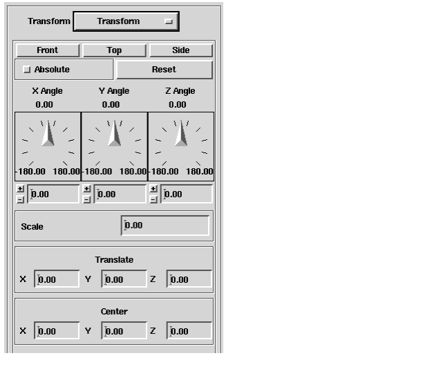
You can use this interface to specify a precise rotation instead of directly manipulating the object with your mouse. With this dialog you can:
- Transform to the Top, Front, or Side
- Transform with Absolute or Relative Values
- Set X, Y, and Z Angle Rotation
- Set Scaling Factor
- Set X, Y, and Z Translation
- Set X, Y, and Z Translation
- Transform the Rotation Center
You can use the Top, Front, and Side buttons to apply a transformation that moves the selected object to the respective position:
- Top rotates so that you are looking down the Y axis
- Front rotates so that you are looking down Z axis
- Side rotates so that you are looking down the X axis.
By default, the transformation you specify is relative to the object's current position. When you open the Transform panel all transformation values are 0. When you enter transformation values, they are interpreted as delta values for the current transformation.
If you set Absolute on, the transformation you specify sets a position in the object's coordinate system. When you first toggle Absolute, the panel reports the current state of the current object: where the object is, how it is rotated, scaled, and where its center is. As you enter transformation values, they are interpreted as locations in the local coordinate system.
You can use the X Angle, Y Angle, and Z Angle dials to specify the degrees of rotation around the respective axis.
The values at the top of the dial show the degrees of rotation to be added to the current transform. When you release the dial the appropriate rotation is added to the object transform and the dial resets to 0. You can also enter a value in the text field below each dial.
If you are in absolute mode (Absolute is on), the dial values display the current transform for the selected object. The values you enter specify absolute degrees of rotation around the respective axis. When you release the dial, the dial does not reset, but stays at the position you set, indicating the current rotation of the object.
You can use the Scale field to set the scaling factor for the current object.
If you are in relative mode, the scaling factor is set to 1.00. You can enter a new scaling factor to change the size of the object in the view.
If you are in absolute mode, the scaling factor indicates the scaling applied to normalize the object from the data coordinates to the view coordinates. You can enter a new scaling factor to change the scaling from world coordinates to the Top view coordinates.
The translate movement along the X, Y, and Z axes. The values are specified in the selected object's local coordinate space. If Top is the selected object, this corresponds to global space, and the transformation applies to all the objects in the view.
If you are in relative mode (The Absolute toggle is off), the translation you specify is relative to the objects current position. That is, the amount of translation you specify is added to the object's current translation.
If you are in absolute mode (Absolute is on), the translation you specify defines a location in the object's local space.
The center of rotation and scaling along the X, Y, and Z axes. By default, the viewer rotates the selected object about its own center. You can use the Center X, Y and Z fields to specify a different center of rotation. The location is specified in the selected object' s local coordinate system.
The Light Editor is an interactive tool with which you can manipulate the lighting in the viewer window.
- About Lighting
- Setting the General Light Attributes
- Specifying Spot Light Attributes
- Manipulating Ambient Light
Two types of lighting illuminate the objects in the viewer window:
- Lights emanating from a specific location. The DataViewer provides four lights of this type, called Light 0, Light 1, Light 2, and Light 3. By default, only Light 0 is on, and it is a white directional light; that is, the direction of the light is parallel to your line of sight, as if a white sun were directly behind you. You also set these lights to be point, spot, or bi-directional lights.
- Ambient light, which does not have a location. An ambient light lights all object throughout the view equally. By default, a white ambient light is on in the viewer window.
By default, both types of lighting are white in color. You can set the color of each light, including the ambient light, independently.
Lights emanating from a specific location are transformable; that is, you can change their location in the same way that you change the location of any object in the viewer window. The distance of a light from an object does not affect its intensity; there is no inverse square law at work. To make a scene brighter, you turn on more lights.
In the remainder of this chapter, the term "light" means a light emanating from a specific source. References to ambient light are always explicit.
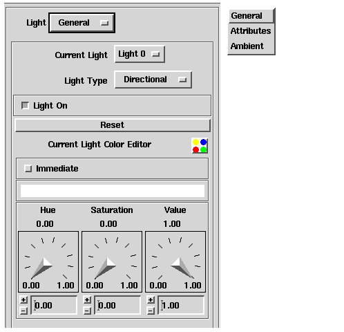
When the Light Editor is first opened, it looks like this:
You can use this dialog to perform the following tasks:
- Specifying the Current Light
- Specifying a Light Type
- Turning a Light On and Off
- Resetting the Attributes of a Light
- Specifying the Color of a Light
The remainder of this section describes the Light Editor tasks.
You use the Current Light buttons to specify the light whose attributes you want to set: Light 0, Light 1, Light 2, or Light 3. Changes you make with the General or Attributes panel of the Light editor, or with the Transform editor when you select the Transform light mode, all apply only to the currently selected light.
By default, each of the four lights is a directional light located directly in front of, facing toward, and an infinite distance away from the object. Only Light 0 is on by default.
A directional light (the default type) is a light source whose rays all point in the same direction; that is, they are parallel. The sun is the canonical directional light source. The initial settings of a directional light are as follows:
- Location: computationally located at infinity along the positive world coordinate Z axis
- Direction: directional vector is 0,0,-1, meaning that the light rays point toward the negative Z axis
A point light is a light source whose rays emanate in all directions from a particular point. A bare light bulb is the canonical point light source. The initial settings of a point light are as follows:
A point light can be inside of an object.
- Note: Point lights are not supported for the software renderer.
A spot light is a light source whose rays emanate from a particular point and are restricted to a 90 degree cone. A flashlight is the canonical spot light source. The initial settings of a spot light are as follows:
- Location: 0,0,0
- Direction: directional vector is 0, 0, -1, meaning that the light rays point toward the negative Z axis
A spot light can be inside of an object.
You can use the Attributes option on the Light editor to set the attenuation, concentration, and spread angle of a spot light.
- Note: Spot lights are not supported for the software renderer.
A bi-directional light is a pair of directional light sources that point in exactly opposite directions. This light is implemented as two lights. The initial settings of a bi-directional light are as follows:
- Location: for the first light, at infinity along the positive Z-axis; for the second light, at infinity along the negative Z-axis
- Direction: for the first light, directional vector is 0, 0, -1, meaning that the light rays point toward the negative Z axis; for the second light, directional vector is 0, 0, 1, meaning that the light rays point toward the positive Z axis
When you transform a bi-directional light, both lights are moved so that they remain opposite one another.
You can use the Light On toggle to turn the current light on or off. When the button is selected (depressed), the light is on; when the button is not selected, the light is off. When you turn a light off, the object at which it points is shadowed; that is, no detail appears.
The Reset bar restores the current light to its default position and color.
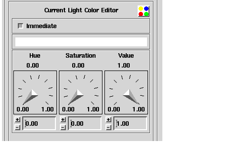
You use the Current Light Color Editor to change the color of the current light:
In this interface, you adjust the Hue, Saturation, and Value dials to specify the hue, saturation and brightness parameters, respectively, of an HSB color space that defines the color of the current light. You can think of an HSB color space as an inverted cone:
- The hue axis runs circularly around the cone. Here are some examples of hue values and the corresponding hues:
- The saturation axis runs from the center of the cone (white) to its perimeter (fully saturated color). Here are some examples of saturation values and the corresponding saturation levels:
- The brightness axis runs from the tip of the cone (black) to the base (white). Here are some examples of brightness values and the corresponding brightness levels:
For a light, the default settings for hue and saturation are 0.00 and the default setting for brightness is 1.00, and the light appears bright white.
By default, changes in the color are not applied until the display is refreshed. You can set the Immediate toggle on if you want to see the effects of the new color immediately.
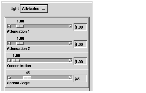
Selecting the Attributes option for a Spot light provides the following user interface:
You use the sliders in this interface to specify two attenuation values, the concentration, and the spread angle of the current light.
- Attenuation of a light source causes objects in the view that are farther from the light source to be illuminated less by the light as they would be in nature. For spot and point lights, the Attenuation values are coefficients that control the loss of light on objects that are farther away from the light source.
The possible range is from 0.00 to 10.00; the default value for both Attenuation 1 and Attenuation 2 is 1.00.
- The Concentration slider controls the lights concentration exponent for spot lights. The concentration exponent is that part of the lighting equation that determines how focussed the light appears in the view. A larger concentration value produces a more highly directional spot; a smaller value simulate a more diffuse light source.
- The Spread Angle slider specifies the angle at which the cone of light spreads out from its location.
- Note: These attributes only apply to spot lights.They are not active for any other type of light.
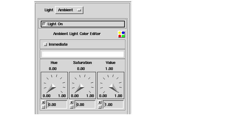
Selecting the Ambient option provides the following user interface:
You use this interface to turn ambient lighting on or off and to specify its color.
By default, ambient light is on in the viewer window. The ambient light provides a uniform, nondirectional, white light throughout the view. Turning on ambient light ensures that an object will always be visible, even if other lights are not illuminating its surfaces. Turning off ambient light increases the contrast between lighted and unlighted surfaces caused by directional lights.
Ambient light has no location. When the DataViewer determines how to portray an object as lit, the value of the ambient light source is always added to the other factors determining the object's lit appearance. Because the ambient light is nondirectional and from no particular source, it does not change the appearance of an object based upon the object's normals. Therefore, if the ambient light source is the only light turned on, the object may appear as a featureless profile of itself.
The Light On toggle on the Ambient panel turns ambient light on or off. When the button is selected (depressed), ambient light is on; when the button is not selected, ambient light is off.
You specify the ambient light color in the same way that you specify color for Lights 1, 2, and 3; that is, you adjust the Hue, Saturation, and Value dials to specify the hue, saturation and brightness parameters, respectively, of an HSB color space that defines the color of ambient light. See Specifying the Color of a Light on page 7-22, for a description of an HSB color space, including examples of the values.
For ambient light, the default settings for hue and saturation are 0.00 and the default setting for brightness is 1.00, and the light appears bright white.
The View Object Editor is an interactive tool with which you can manipulate the basic properties of one or more of the objects in the view.
- Specifying an Object's General Attributes
- Specifying Field Conversion Methods
- Set Image Data Conversions
- Setting Texture Conversions
- Selecting Rendering Modes
- Specifying View Object Properties
- Specifying a Texture Mapping
When you select Object from the Editors menu in the DataViewer menu bar, AVS/Express displays the following interface:
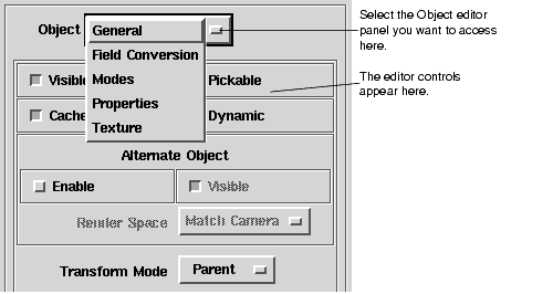
You use this dialog box to set properties for the currently selected object.
You can choose the following options from the Object option menu:
- General - Set basic object properties including, visible, pickable, cached, and dynamic. Enable and control an alternate object. Set the transform mode to Parent, Normal or Alternate. See Specifying an Object's General Attributes7-28
- Field Conversion - Set conversion properties for field data for lines and surfaces, images, or textures. See Specifying Field Conversion Methods7-30
- Modes - Set rendering modes for points, lines, surfaces, volumes, bounds, and normals See Selecting Rendering Modes7-37
- Properties - Set the object's primary, secondary, and tertiary colors. Set rendering characteristics for points and lines, surfaces, and volumes.See Specifying View Object Properties7-40
- Texture - Set textures characteristics for interpolation, tiling, blending, and rendering type (single level or mip-map). See Specifying a Texture Mapping7-50
Choose General from the Object option menu to display the following dialog box:
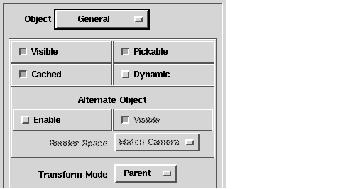
- Set Object Properties Visible, Pickable, Cached, and Dynamic
- Enable the Alternate Object
- Set the Transform Mode
You can use the Visible button to control whether the currently selected object is visible or not. By default, objects are visible and the Visible button is depressed. Click the button to make the object invisible. The button appears raised.
When a object is invisible it remains in the view. You cannot select it by picking it in the view, but you can select it by using the Object Selector and then edit its characteristics even though it cannot be seen.
Note that when an object is not visible, all its children objects are also not visible. For example, if you select Top and set its visibility off, all the objects in the Top hierarchy are made invisible. You cannot make them visible again until to set the visibility of Top on again.
You can use the Pickable button to control whether the currently selected object is pickable. By default the object is pickable, and the Pickable button is depressed. Click the button to make the object not pickable. The button appears raised.
When an object is pickable, you can select it by pointing at it with your mouse and pressing CTRL-MB1.
Note that when an not pickable, all its children objects are also not pickable.
You can use the Cached button to control whether AVS/Express should cache the currently selected object's data. By default the object is cached and the Cached button is depressed. Click the Cached button to disable caching; the button appears raised.
Caching saves a geometrical representation of the data being rendered. The method of caching depends on the renderer you are using. Caching will generally speed up rendering of the view, but note that if an object is rendered in multiple views with different renderers enabled, there are multiple caches. If the data being rendered is large, caching can use large amounts of memory.
You can use the Dynamic button to control whether the currently selected object is marked as static or dynamic for accelerate mode rendering. You set accelerate mode by setting the Accelerate button on the View editor's Options panel.
When accelerate mode is set on for the view, the renderer(s) store the image and Z-buffer information for static-type objects. When dynamic-type objects are changed, they are re-rendered into the buffers already containing the rendered static objects - the static object need not be re-rendered unless it is also changed.
You use the Alternate Object controls to enable and configure an alternate object that can be used in place of the selected object during transformation. Using a simpler object for transformations can speed-up rendering. By default, the alternate object is disabled.
To use the alternate object, set the Enable button on. When the alternate object is enabled and you directly manipulate the object in the viewer window, AVS/Express displays the object's bounding box in place of the object. You can use the bounding box to transform the object to the position you want. When you release the mouse to end the transform, AVS/Express removes the bounding box and re-displays the object in its new position.
You can use the Render Space options, Match Camera or Force 2D, to choose how the alternate object is rendered:
- Match Camera - AVS/Express renders the alternate object in the same space as the current camera.
- Force 2D - AVS/Express renders the alternate object in 2D space with 2D primitives.
You can use the Transform Mode options to control where the transform is calculated when you are directly manipulating the object in the viewer window. You can choose the following options:
- Normal - Edit the transform of the object itself.
- Parent - Edit the transform of the object's parent using the parent's transform mode.
- Alternate - Edit an alternate transform of the object.
When you select Field Conversion from the View Object editor's option menu, AVS/Express displays the following interface:
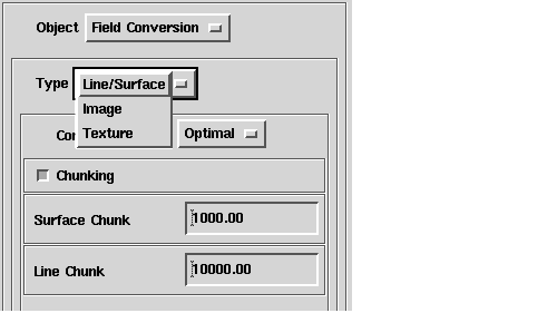
You can use the Field Conversion dialog to control how AVS/Express converts field data representing lines and surfaces, images, or textures into rendered objects. You can use this dialog to:
When you choose Line/Surface from the Type option menu of the Field Conversion editor panel, AVS/Express displays the following dialog:
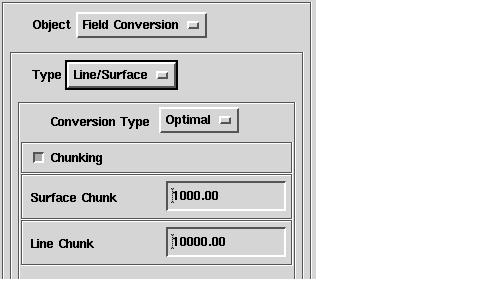
If the cell type of the field you are reading into the viewer is a triangle, quad, or polyhedron, you can use the Conversion Type options to control how the surface data is converted into a triangle strip for rendering. You can choose the following options
- Simple - AVS/Express constructs the triangle strip to represent the surface by adding zero-area triangles. For example, using this simple method, AVS/Express converts field data containing 10,000 triangles into a triangle strip of 60,000 triangles.
- Optimal - AVS/Express rearranges the list of cells in the field data to construct a triangle strip that represents the surface more efficiently. For example, using the optimal method, AVS/Express converts field data containing 10,000 triangles into a triangle strip of 20,000 triangles. The amount of optimization AVS/Express can achieve depends on the number of shared nodes in the input field.
- None - AVS/Express supports the direct rendering of triangles and quad surfaces (available with Open GL) without converting them to triangle strips.
The Optimal conversion can produces a surface representation that is smaller, but it takes more time and uses more temporary memory than the Simple method. The bytes of temporary storage needed by the optimal conversion can roughly be calculated by multiplying the number of triangles by 240. None reudces the memory usage and can improve performance when the data is changing
You can use the Chunking button to enable and disable chunking during the conversion of field data. If chunking is on, AVS/Express converts the data in groups rather than all at once. If you set Chunking off, the whole surface is converted in one operation.
You specify the number of primitives that are rendered in one chunk by setting the Surface Chunk and Line Chunk values:
- Surface Chunk - The number of cells to process at one time when chunking is enabled and a surface rendering mode is selected.
- Line Chunk - The number of cells to process at once when chunking is enabled and a line rendering mode is selected.
When you select Image from the Type options on the Field Conversion panel, AVS/Express displays the following interface:
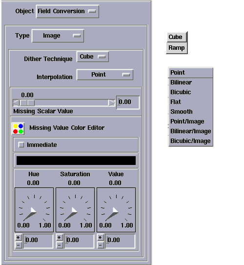
You use this dialog to control how field image data is rendered into an 8-bit visual. If you use a 24-bit visual, AVS/Express directly renders the colors. You can perform the following tasks:
You can use the Dither options to choose the Cube or Ramp dithering technique:
If you choose Cube, AVS/Express converts the scalar image values to RGB color values and then dithers them.
If you choose Ramp, AVS/Express converts the datamap to a linear ramp of color values in the system palette and then uses the ramp to convert the image values directly to pixels.
If you choose Point, AVS/Express uses point sampling to interpolate between image values. Other interpolation options include Bilinear, Bicubic, Flat, Smooth, Point/Image, Bilinear/Image and Bicubic/Image.
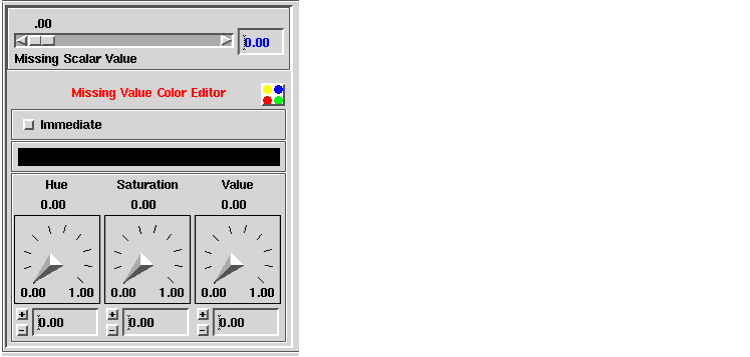
You can use the lower portion of the Image editor panel to specify scalar and color values to replace missing values in the image
Use the Missing Scalar Value slider to specify a value. AVS/Express uses this value to replace areas of scalar images that are "left empty" when the image is rotated.
Use the Missing Color Editor to define the components specifying a color. AVS/Express uses this color to render areas of RGB images that "left empty" when a tiled image is rendered.
For information on using the color editor, see Set an object's colors and jitter on page 7-42
If the Immediate button is set on, the view is updated continuously as you enter changes into this editor. If you set the Immediate button off, the update is delayed until you complete the operation.
*note* this option is for 2D scenes and has no effect in 3D scenes.
When you select Texture from the Type options on the Field Conversion panel, AVS/Express displays the following interface:
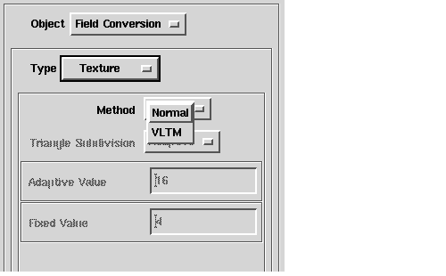
You can use this dialog to choose the Normal method, or to choose and configure the VLTM (Vertex Level Texture Mapping) method.
For more information about VLTM, see the section on XGL Renderers in the Installing AVS/Express manual.
If you choose Normal, AVS/Express uses its standard texture mapping mechanism. You can control how this method is applied by choosing the Texture option from the Object editors option menu. See Specifying a Texture Mapping on page 7-50
If you are using a SunOS5 platform running the ZX graphics boards with the XGL renderer, you can VLTM (Vertex Level Texture Mapping). For this method, you can choose two types of triangle subdivision:
- Adaptive - If you choose Adaptive from the Triangle Subdivision option menu, you set the Adaptive Value field. This value specifies the pixel tolerance level when the texture mapping subdivision type is adaptive. In this mode, the triangles are subdivided until the tolerance level is reached.
- Fixed - If you choose Fixed from the Triangle Subdivision option menu, you set the Fixed Value field. This value specifies the number of segments when the texture mapping subdivision type is fixed. In this mode, each triangle is subdivided by the number of segments specified.
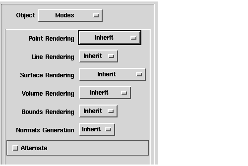
If you choose Modes from the Object option menu, AVS/Express displays the following interface:
You use this interface to specify the modes used to render the polygons that make up the current object and the object's bounding box. A separate group of modes is provided for each of the following:
- the points in the polygons
- the lines in the polygons
- the surfaces of the polygons
- the object's bounding box
You use the Point Rendering option menu to select the point rendering style. The following modes are available:
- Inherit - The current point mode is replaced with that of the object's parent. This is the default.
- None - The points are not rendered in the Viewer window.
- Pixel - the points are rendered as pixels.
- Line Directed - The points are rendered as lines normal to, and directed outward from the points.
- Arrow Directed - The points are rendered as lines normal to and directed outward from the points.
- Cone Directed - The points are rendered as cones normal to and directed outward from the points.
- Cross Tangent - The points are rendered as crosses tangent to, and directed according to the connectivity defined for the polygons in the object.
You use the Line Rendering option menu to select the line rendering style. The following modes are available:
- Inherit - The current line mode is replaced with that of the object's parent. This is the default.
- None - The lines are not rendered in the viewer window.
- Regular - The lines are rendered as lines.
- Tube - The lines are rendered as tubes.
- Arrow - The lines are rendered as arrows directed according to the connectivity defined for the polygons in the object.
- Ribbon - The lines are rendered as flat ribbons.
You use the Surface Rendering option menu to select the surface rendering style. The following modes are available:
- Inherit - The current surface mode is replaced with that of the object's parent. This is the default.
- None - The surfaces are not rendered in the viewer window.
- No Lighting - The surfaces are rendered with no shading in the surface color.
- Flat Shading - The surfaces are rendered with flat shading. Flat shading shades the surface of each polygon in the surface color.
- Gouraud Shading - The surfaces are rendered with Gouraud shading. Gouraud shading blends the colors of the polygon's points across its surface, simulating smooth shading.
- Background - Render using the background color (thus hiding the surface and items behind it)
You use the Volume Rendering option menu to select the volume rendering style. The following modes are available:
- Inherit - The current volume mode is replaced with that of the object's parent. This is the default.
- None - The volume is not rendered in the viewer window.
- BTF Texture - The volume is rendered using the back-to-front volume rendering technique. BTF rendering is only available if you are using the software renderer.
- Ray Tracer - The volume is rendered using a ray-tracing technique.
You use the Bounds Rendering option menu to select the bounds rendering style. The following modes are available:
- Inherit - The current bounding box mode is replaced with that of the object's parent. This is the default.
- None - The bounding box is not rendered in the viewer window.
- Bounds - The framework (lines and points) of the bounding box are rendered in the Viewer window.
You use the Normals option menu to select whether normals will be generated for the object. The following modes are available:
- Inherit - The current Normals mode is replaced with that of the object's parent. This is the default.
- None - Normals are not generated.
- If normals are explicitly included as part of the object's data, for example as geometry data, the normals will be rendered by the viewer.
When you select Properties from the Object editor's option menu, AVS/Express displays the following interface:
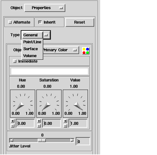
You use this dialog to set color and jitter properties for the currently selected object, and specific properties for points and lines, surfaces, and volumes. The following tasks are define below:
- Set an object's colors and jitter
- Specifying point and line properties
- Specifying surface properties
- Specifying volume properties
You select General from the Type option menu on the Object Properties panel to
You can use the Primary Color, Secondary Color, and Tertiary Color options on the Object Color option menu to specify primary, secondary, and tertiary colors for different components of the current object:
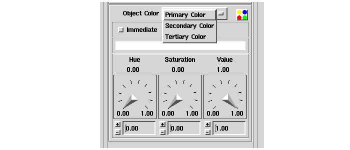
AVS/Express applies the primary, secondary, and tertiary colors you specify to the points, lines, and surfaces components of the polygons that make up the object in the order in which you specify rendering modes for them. You specify the rendering modes by selecting Modes from the Object editor option menu.
For more information about setting rendering modes, see Selecting Rendering Modes on page 7-37
Specifically, the colors are assigned as follows:
- The primary color is applied to the first component for which you specify a mode. The primary color is white by default.
- The secondary color is applied to the second component for which you specify a mode. The secondary color is white by default.
- The tertiary color is applied to the third component for which you specify a mode. The tertiary color is red by default.
For example, if you select a mode for surfaces, then for points, and then for lines, the primary color is assigned to the surfaces, the secondary color is assigned to the points, and the tertiary color is applied to the lines. The color of the surfaces is applied to the bounding box.
The color scheme used to define colors for an object is an HSB color space. An HSB color space allows you to specify three parameters that define the color: the hue, the saturation, and the brightness. You can think of an HSB color space as an inverted cone:
- The hue axis runs circularly around the cone. Here are some examples of hue values and the corresponding hues:
- The saturation axis runs from the center of the cone (white) to its perimeter (fully saturated color). Here are some example s of saturation values and the corresponding saturation levels:
- The brightness axis runs from the tip of the cone (black) to the base (white). Here are some examples of brightness values and the corresponding brightness levels:
For an object, the default settings for hue and saturation are 0.00 and the default setting for brightness is 1.00, and the object appears bright white.
You use the Jitter slider to specify an offset in the object's depth position in the view. Positive jitter values bring the object forward in the view, and negative jitter values moves the object to the back.
Jitter is useful when you want to offset an object in relation to other objects in the view in order to resolve ambiguity in rendering the depth of objects that occupy the same plane. For example, you can apply a jitter to isolines you add to a surface, or to axes you add to a slice, in order to ensure that the lines are rendered without breakup.
- Note: The jitter offset only changes the position of the object in view space. It does not affect the position of the object in local or global space, or transformations that you have applied to the object. Operations such as picking or clipping are still performed based on the position of the object in global space. This can cause some unexpected results. For example, in some renderers an object that is displayed in front of another object in the view because of the jitter applied to it, may be clipped before the object that appears to be behind it.
When you select Point/Line from the Type option menu, AVS/Express displays the following interface:
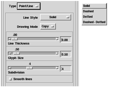
In this interface, you assign values for the properties of the points and lines in the polygons that make up the current object. These properties are applied when you select a rendering mode that displays lines or points. You can use this dialog to set the following properties:
- Line Style - Specify the pattern used to draw the lines. You can choose Solid (the default), Dashed, Dotted, or Dashed-dotted (an alternating pattern of dashes and dots).
- Drawing Mode - Specify how the line is drawn against the existing objects or background. You can choose:
- Line Thickness - Specify the thickness of the line in number of pixels.
- Glyph Size - Specify a scaling factor for the glyphs displayed at each vertex when a Point Rendering mode is set. For example, if you choose the Line Directed point rendering mode, you can use Glyph Size to adjust the length of the lines at each point.
- Subdivision controls the number of polygons used to represent a sphere when you are using the software renderer or a hardware renderer that does not represent spheres directly. If you increase Subdivision, the rendering of spheres is improved but takes longer and uses more memory.
When you choose Surface from the Type option menu, AVS/Express displays the following interface:
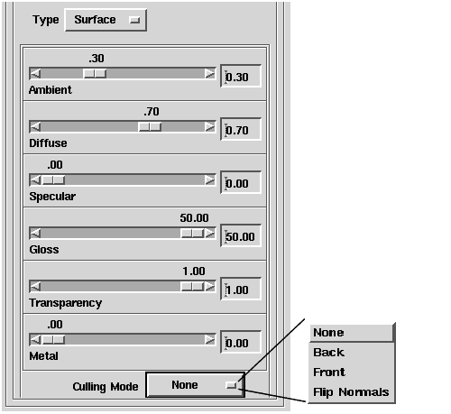
You use this dialog to set the reflectance properties of the current object's surface. You can set these properties to simulate the appearance of different materials. You can perform the following tasks:.
- Set the ambient light reflectance
- Diffuse light reflectance
- Intensity of the specular highlights
- Gloss of the specular highlights
- Transparency
- Metal
- Culling mode
You can use the Ambient slider to set the ambient light reflectance. The ambient light reflectance is the proportion of the available ambient light that the object reflects. The Ambient slider specifies the proportion of ambient light the object reflects; 0 is none and 1.00 is all.
You can use the Diffuse slider to specify the diffuseness of the non-ambient light. The diffuse light reflectance is the proportion of the available non-ambient light that the object reflects equally in all directions. Non-ambient light emanates from directional and point light sources, which you specify with the Light Editor. This value is used in the calculations for flat and Gouraud shading.
You can use the Specular slider to specify the intensity (brightness) of the specular highlights. Specular highlights of a particular color and brightness are created when the direction of incoming light (from a directional or point light source) is "sufficiently close" to the viewing direction.
You use the Gloss slider to specify the gloss (sharpness) of the specular highlights.The gloss is the sharpness of the specular highlights. The greater the sharpness of a specular highlight, the smaller (more focused) is its size.
You use the Transparency slider to control the transparency of the currently selected object. The value ranges between 0.00 and 1.00. As Transparency approaches 0, the object's surface gets more transparent. As Transparency approaches 1.00, the object's surface gets more opaque.
You use the Metal slider to give the surface of the object a metallic sheen by controlling the color of the specular highlights. The slider specifies the color used to render specular highlights as a combination of the color of the light source and the color of the object. Setting the value closer to 0.00 produces specular color nearer the color of the light source. Setting the value closer to 1.00 produces a specular color nearer the color of the object.
The Culling Mode option menu controls how the backfacing and frontfacing polygons in the current object are drawn.
Backfacing polygons are those facing away from the user and frontfacing polygons are those facing toward the user. The direction in which a polygon is facing is determined by the order of its vertices or the direction of its vertex normals.
The following culling modes are provided (availability is renderer dependent):
- None - No culling takes place.
- Back - The render does not draw backfacing polygons. If an object is completely enclosed, you may not see any change when you cull the backfacing polygons.
- Front - The renderer does not draw frontfacing polygons.
- Flip Normals - The renderer reverses the vertex normals and lights back faces like front faces.
When you select Volume from the Type option menu, AVS/Express displays the following interface:
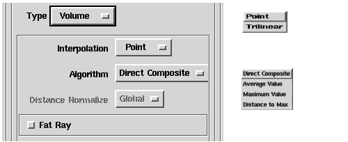
You can use this dialog to control the following volume properties
You use the Interpolation option menu to specify how voxel values are mapped to rays or pixels. You can choose from the following options:
- Point - The value of the nearest voxel is used.
- Trilinear - Values are linearly interpolated for the two nearest voxels in each of the 3 principal directions. In mode BTF, this degenerates to a bilinear interpolation within a 2D texture slice.
For volume mode Ray Tracer (SW renderer only) the mapping from voxels is performed at each step along the ray. For volume mode BTF (OpenGL renderer only) the interpolation from voxels to pixels uses an intermediate mapping through textured slices. For more information on BTF see 'System Prerequisites - Rendering Across Platforms'.
When you are using the Ray Tracer volume mode (software renderer only), you can use the Algorithm option menu to specify how data or spatial values are mapped to the ray, and how the ray values are mapped to a final color for the pixel.
- Direct Composite - At each step along the ray, the interpolated voxel value is looked up in the datamap, and the resulting RGBA values are composited with the current RGBA of the ray using standard alpha blending equations.
- Average Value - The ray maintains a moving average of the voxel values along its length. The averaged value of the completed ray is then looked up in the datamap.
- Maximum Value - The ray maintains the maximum value encountered along its length. The final value of the completed ray is then looked up in the datamap.
- Distance to Max - The ray maintains a distance measure and the maximum value. The distance is only updated when a new maximum value is encountered. The final distance value is normalized according to the Distance Normalize flag (see below), then looked up in the datamap.
- Distance Normalize: When you are using the Ray Tracer volume mode (SW renderer only). and the Distance to Maximum algorithm method, you can use the Distance Normalize option menu to determine how the ray ranges are normalized. You can choose from the following options:
- Global - The ray ranges are normalized to the diameter of a sphere enclosing the volume. This means that the normalization and datamapping are the same for all rays in all views of any given dataset.
- View - The ray ranges are normalized to the depth of the current view. This depth is the maximum extent of the data volume projected onto the viewing direction (i.e. the length of the longest ray). The depth, and hence the normalization, will vary for each different orientation of the volume.
- Ray - The ray range is individually normalized to the length of the ray. This means that in principle, each ray has a different normalization, but in practice, large regions of the rendering will have similar length rays, especially for large flat volumes.
For volume mode Ray Tracer (SW renderer only) this flag enables a super-sampling method that traces a single ray through a 4x4 block of pixels. The resulting image is faster to render, but of lower resolution.
When you select the Texture from the Object editor option menu, AVS/Express displays the following interface:
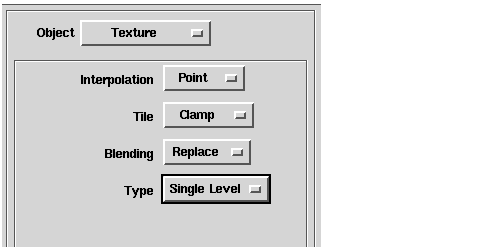
You can use this interface to control how a texture is applied to the currently selected object. You can set the following properties:
- Setting the interpolation method
- Setting the tile method
- Setting the texture blending method
- Setting the texture map type
You can use the Interpolation option menu to control how the texture map is mapped to the surface of the object. You can choose from the following options:
- Point - The texture map is sampled at a single point to determine a value for the corresponding pixel of the object's surface.
- Bilinear - Performs bilinear sampling of the texture map values and interpolates a pixel value for the object's surface.
- Trilinear - Performs trilinear sampling of the texture map values and interpolates a pixel value for the object's surface.
Each successive interpolation method produces a smoother mapping of the texture to the surface, but at a higher cost to performance. The bilinear and trilinear methods are not available on all renderers.
You use the Tile option menu to control what happens when the texture map's coordinate values are outside the 0-1 range. You can choose the following options:
- Clamp - Clamp UV(W) values that are outside the 0-1 range. Render using the primary color.
- Wrap - Wrap UV(W) values that are outside the 0-1 range.
- Boundary - Clamp UV(W) values that are outside the 0-1 range, but render using the value at the texture's boundary
You can use the Blending option menu to control how the texture map is combined with the existing surface of the object. You can choose from the following options:
- Replace - The texture map values replace the object's pixel values on the surface.
- Modulate - The texture map values and the object's pixel values are combined. This means that the object's color affects the appearance of the texture when it is applied to the surface.
- Decal - The application of the texture to the surface is controlled by the alpha value for each pixel.
You can use the Type option menu to choose the You can choose from the following options:
- Single-level - Creates an unfiltered texture map.
- MIP Map - Creates a texture map using multi-level filters.
You view the images in the viewer window through a camera. You can manipulate the camera to control such things as the point of view, perspective rendering, clipping planes, and depth cueing.
- Setting the Camera General Attributes
- Setting the Camera Lens
- Setting the Camera Tripod
- Setting the Camera Clipping Planes
- Setting the Camera Depth Cueing
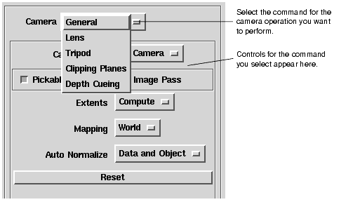
When you select the Camera option from the Editors menu, AVS/Express loads the following editor panel:
You can use this panel to select the following options from Camera option menu:
- General - Select 2D or 3D camera and specify additional options: pickable, image pass, extents, mapping, and auto normalize. See Setting the Camera General Attributes7-55
- Lens - Specify the camera lens: Toggle between parallel and perspective viewing projections and set the characteristics of the selected projection. See Setting the Camera Lens7-57
- Tripod - Specify the position of the camera's tripod, which defines the position of the camera in world space. See Setting the Camera Tripod7-61
- Clipping Planes - Turn clipping on or off and set the position of the clipping planes. See Setting the Camera Clipping Planes7-62
- Depth Cueing - Turn depth cueing on and off, and set the depth cueing planes and scaling. See Setting the Camera Depth Cueing7-63
The remainder of this chapter describes the Camera Editor tasks.
You look upon a world space through a camera. The view that the camera sees comprises the contents of the viewer window.
You can think of the camera as being mounted on an adjustable tripod; the position of the tripod defines the location of the camera in world space. Initially, the camera is located at about (0,0,12) in world space, looking toward the origin along the Z axis.
Through its lens, the camera sees a view volume. By default, the view volume is a parallel (orthogonal) viewing projection: an oblong box extending from the camera's location to infinity along the Z axis. The initial view volume is a rectangular subset of world space extending from +5 to -5 X, from +5 to -5 Y, and from +100 to -100 Z in world coordinates.
The view volume travels with the camera as it is moved about world space. Therefore, the camera has its own coordinate system, sometimes called camera coordinates. The camera is always looking from the positive Z axis of camera coordinates toward the negative Z.
When using the camera, one sometimes speaks of translating the camera, scaling it (zooming in and out), and rotating it. This terminology is somewhat misleading. What is really happening is that world space is being rotated, scaled, and translated in order to fit within the camera's view volume.
You can change how the camera views the scene in the viewer window in several ways.
- You can change the shape of the camera's view volume by specifying that the lens uses a perspective projection rather than the default parallel projection. Turning on perspective changes the shape of the view volume from a box to a frustum (see Specifying the lens' viewing projection on page 7-58).
- You can change the location of the camera in world space (see Specifying the tripod's position on page 7-61).
- You can change the length of the camera's view volume by turning on clipping. Turning on clipping activates front and back clipping planes that truncate the view volume at front and back (see Setting the Camera Clipping Planes on page 7-62).
- You can specify that the scene in the viewer window is rendered using depth cueing. Turning on depth cueing causes objects to appear to fade into the background color as they become more distant from the camera (see Setting the Camera Depth Cueing on page 7-63).
Note that the camera view volume's Z=0 plane can intersect world space from any angle. This intersection is called screen space or screen coordinates. When you translate objects and lights using "direct manipulation" movements with the workstation's mouse buttons, the transformables move with respect to the camera's view volume, not world, Top, or object-level coordinates. By and large, this is a distinction that you can ignore. You will usually only notice it when you use direct manipulation on objects such as the arbitrary slicer module's slice planes or the probe module's pointer. When you move the slice plane, for example, in the Z direction, the slice plane moves straight toward or away from the camera (camera's Z axis), not along the object's Z axis.
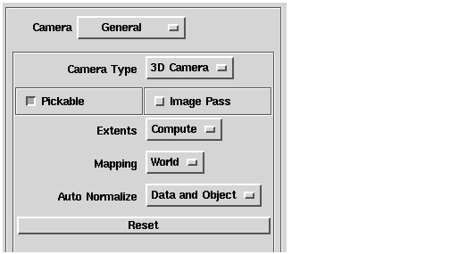
When the Camera Editor is first opened, it looks like this:
- Select the camera type
- Make a camera pickable.
- Enable a separate image render pass.
- Set normalization extents
- Controlling the camera mapping.
- Setting the auto-normalize event.
Pressing Reset returns all the camera parameters to their default values.
You can use Camera Type option menu to choose 3D Camera or 2D Camera.
By default, the 3D Camera is located directly above and facing downwards toward the object, at a position of about 0, 0, 12 in world space.
To make a camera pickable or not pickable, set the Pickable button on or off. By default the camera is pickable.
When the camera is pickable you can select objects in the view by pointing at the object with your mouse, and pressing the Control key and the left mouse button.
When the camera is not pickable, all the objects in that camera cannot be picked.
You can use this option if there are objects in the view, such as annotations or legends that should not be transformed.
Set the Image Pass button on to cause AVS/Express to render the images in 2D cameras in a separate pass. If you enable a separate image pass, images are rendered "behind" the other objects in the camera.
If you set the Image Pass button off, the renderer does not make a separate image pass. All objects in the camera are rendered in the order that they were attached to the camera.
You can use the Extents options to control how AVS/Express computes the extents of the objects when normalizing the view:
- Select the Compute option to cause AVS/Express to compute the extents from the objects' data.
- Select the Window option to cause AVS/Express to determine the object's extents from its window.
You can use the Mapping options to control how the object data in the camera is mapped to the view.
- Select the World option to map the object data in the camera to world space.
- Select the Pixel option to map the object data to pixel space. This setting sets the camera's scale factor to the camera's number of pixel's divided by 2. This setting is particularly useful for image data.
You can use the Auto Normalize options to control if and when the objects in the camera are normalized to fit in the view.
- Select None to disable auto-normalization.
- Select Data Change to cause AVS/Express to normalize the view whenever the object's data extents change.
- Select Object Attach to cause AVS/Express to normalize the view whenever a new object is attached to the camera.
- Select Data and Object to cause AVS/Express to normalize the view whenever either the object's extents change or a new object is attached to the camera.
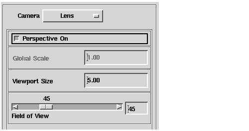
Selecting the Camera Lens button in the Camera editor displays the following user interface:
You use this interface to switch between parallel and perspective viewing projections and to set the characteristics of the projection used.
By default, the camera's lens uses a parallel (orthogonal) viewing projection. A parallel viewing projection provides a view volume that can be represented as an oblong box extending from the camera's location to infinity along the Z axis.
Turning on perspective causes the lens to use a perspective viewing projection instead. With perspective turned on, the camera's view volume changes from a rectangle to a frustum (a squared-off cone). The portions of objects in front of the view volume's Z=0 plane are uniformly exaggerated in size as they approach the camera and uniformly diminished behind the Z=0 plane.
A perspective projection gives a more real-world rendering of objects than a parallel projection. You may need to turn on perspective for your eye to be able to interpret a scene.
You can modify the degree of perspective exaggeration with the Field of View slider. Perspective also affects the apparent location of the camera. The camera seems to be much closer to the object, and its clipping planes are similarly shifted inwards.
You can make a camera appear to zoom inside an object by turning perspective on, then Z translating the camera or object with the shift-middle mouse button.
The Perspective button controls whether or not the camera lens uses a perspective projection:
- Set the Perspective button on to cause the camera lens to use a perspective projection
- Set the button off to cause the camera to use a parallel projection. This is the default setting.
You can also turn perspective on or off in the view by clicking the Perspective icon in viewer window toolbar. By default, perspective is off and the icon looks like this:
When you click on the icon, perspective is turned on in the view and the icon changes to look like this:

The Camera->Perspective command toggles between perspective and parallel viewing projections for the 3D camera. When the Perspective button is selected (depressed), the perspective viewing projection is used. When the button is not selected, the parallel viewing projection is used.
In the perspective viewing projection, the portions of objects in front of the XY-plane are uniformly exaggerated in size as they approach the camera, and are uniformly diminished behind the plane, as in the following figure.
Perspective projection attempts to approximate how the human eye views an object, and therefore gives a more "real-world" rendering of the object.
In the parallel viewing projection (the default), the object size is consistent overall: as in the following figure.
A parallel viewing projection is also called an orthogonal projection.
You use the three remaining controls, the Global Scale and Viewport Size fields, and the Field of View slider, to set the characteristics of the viewing projection.
- Set Global Scale to specify the factor by which the size of the object in the viewer window is magnified or shrunk:
When the object in the Viewer window is scaled, the scale factor is applied before other parameters (such as front and back clip). Therefore, if you specify a scale factor other than 1.0, you will need to scale the other parameters by the same factor to get values in world coordinates.
- Set Viewport Size to specify the scale factor that determines the range of viewing in a parallel projection. The Viewport size is defined in world coordinates. The default value is 5.00.
- Use the Field of View slider or enter a value in the field to specify the angle formed by the edges of the view volume for perspective projections. The possible range is from 1 to 180 degrees; the default value is 45 degrees.
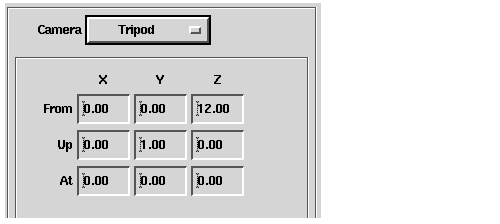
Selecting the Tripod option from the Camera menu in the camera editor displays the following user interface:
You use this interface to specify the position of the tripod on which the camera is mounted. Specifying the tripod position defines the position of the camera in world space.
You specify the position of the tripod in terms of three camera position parameters called From, Up, and At.
This point contains the X, Y, Z position of the camera in world coordinates. In both parallel and perspective projections, it defines the base point for the front and back clipping planes and the depth cueing parameters. If perspective is turned on, it is the "eye" position of the camera.
This direction vector determines the direction of the vertical axis of the camera. A line that is parallel to the Up vector in world coordinates will be drawn as a vertical line in the window. It is important that this direction vector be perpendicular to From to At (the view direction) or the camera will "shear" the objects.
This point is used in conjunction with the From point to determine the view direction (Z axis) of the camera. A line in world coordinates that connects From to At will be drawn as an end-on line directly in the middle of the camera window.
You use the grid in the interface to set the position parameters. Each parameter requires the X, Y, and Z coordinates in world space of the point or vector. Recall that the Up vector originates at the From point, which is not necessarily the origin in world space.
Selecting the Clipping Planes options from the Camera editor menu displays the following interface:
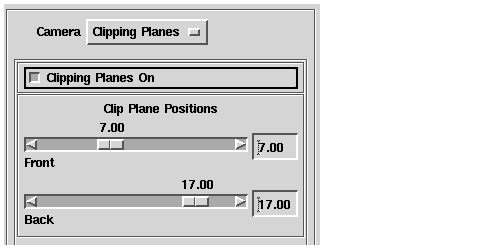
You can turn clipping on or off by setting the Clipping Planes On button. You use the sliders to specify the locations of the front and back clipping planes.
When you turn on clipping, you activate two clipping planes that truncate the view volume of the camera. Objects in front of or behind the two clipping planes are not rendered in the view window.
When clipping is enabled, objects disappear as they move either very close to the eyepoint or very far away. When clipping is disabled, the front and back clipping planes are still present but are so distant that in most cases no front/back clipping takes place. Simply put, turning clipping off puts the clipping planes very near the camera itself and turning clipping on puts the clipping planes near the scene.
The actual location of the clipping planes depends upon how the camera has been scaled and whether a perspective projection is in use (see Specifying the lens' viewing projection on page 7-58). Clipping is defined in the camera's view volume, not in world coordinates.
The Clipping Planes On button turns clipping on or off. When the button is selected (depressed), the clipping planes are near enough to the scene to have an effect; when the button is not selected, the clipping planes are so distant as to have no effect.
You set the location of the clipping planes with the Clip Plane Positions Front and Back slider bars. When the camera is first created, the clipping planes are located as follows:
- When clipping is turned off, the front and back clipping planes are located at Z=0 and Z=100 in camera coordinates, respectively. If you change from a parallel to a perspective projection, the clipping planes move inward to about Z=1 and Z=100.
- When clipping is turned on, the front and back clipping planes are located initially at Z= 7 and Z=17 in camera coordinates for both parallel and perspective projections.
The values of the slider bars can range from 0 to 100 for either clipping plane. By default they are set to -88 and 112. You should ensure that the value of Front is smaller than the value of Back, otherwise there will be an overlap and the entire contents of the view volume will be truncated.
When using both clipping and depth cueing, note that the Front clip plane position is usually smaller than Front Depth Cue and the Back clip plane position is usually larger than Back Depth Cue.
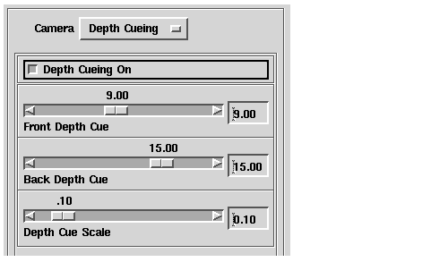
Selecting the Depth Cue option from the Camera menu in the camera editor displays the following user interface:
You use the Depth Cueing On button to turn depth cueing on or off. You use the sliders to specify the location of the depth cue planes and the depth cue scaling factors.
Depth cueing is a visual effect that causes lines or other objects in the camera's view volume to appear to fade into the background color as they get more distant from the viewing position. This effect enhances the illusion of three-dimensional depth in the viewer window. You can adjust depth cueing by specifying where it begins and ends and how much fading is applied.
Note: The types of objects that are affected by depth cueing depends on the type of renderer you are using. The software renderer supports depth cueing of lines. The hardware renderers that come with various systems may support depth cueing of lines, polygons, and/or spheres.
The Depth Cueing On button turns clipping on or off. When the button is selected (depressed), depth cueing takes place; when the button is not selected, depth cueing does not take place.
You set the characteristics of depth cueing with the Front Depth Cue, Back Depth Cue, and Depth Cue Scale slider bars.
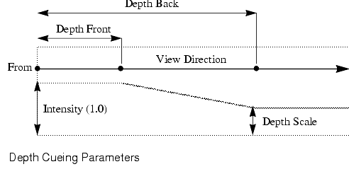
This value specifies the distance in front of the From point in the viewing direction (towards At) where depth cueing begins. Any objects that are closer to the From point than this distance will be drawn at full intensity.
For more information about the From, At, and Up camera positions, see Setting the Camera Tripod on page 7-61
This value specifies the distance in front of the From point in the viewing direction (towards At) where the maximum depth scale is applied.
This value is the factor that is applied to locations farther from the viewer than the Front Depth Cue plane. The scaling factor controls the rate at which the color intensity is decreased from the Front Depth Cue plane to the Back Depth Cue plane.
The following figure illustrates the relationships between the depth cueing parameters and the camera's position parameters.
When using both depth cueing and clipping, note that Front Depth Cue should usually be larger than Front clip plane position, and Back Depth Cue should usually be smaller than Back clip plane position.
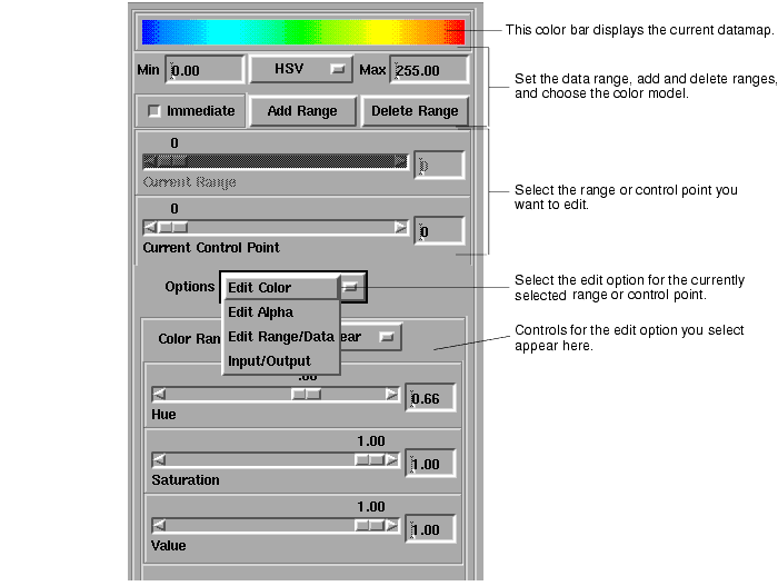
A datamap converts scalar node data or cell data values to RGB colors.
- Specify a Data Range
- Defining the Color Mapping
- Defining the Current Alpha Map
- Reading Datamap Files
When you first open the Datamap editor it looks like this:
You use this interface to perform the following tasks
- Specify a Data Range
- Defining the Color Mapping
- Defining the Current Alpha Map
- Reading Datamap Files
For more information about how datamaps are specified, see Understanding Datamaps
The datamap controls how data values in the input data are converted into the color values that are rendered in the view. You define a range of data and specify control point colors that are associated with minimum and maximum data values. If you specify a linear color range mapping, AVS/Express interpolates a range of colors between the control point colors and assigns them to the range of data values. If you specify a step mapping, AVS/Express assigns a constant color to each step you define and assigns the color to the data points that fall in the range of the step. You can also specify multiple ranges in the data and assign control point colors to each.
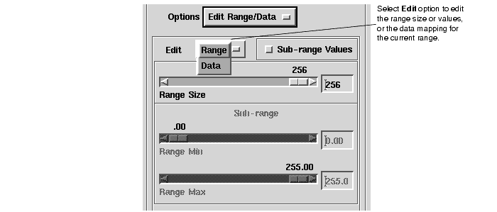
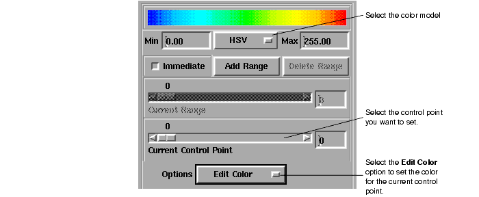
You use this editor to define a range, or multiple ranges of data values, and the color model (RGB or HSV) you want to use to specify color values. Then, for each range you define the size of the range (that is, the number of color steps to use in the mapping), the color map to be associated with the range, and, optionally, a mapping for alpha values to be assigned to the data values.
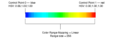
For example, if you define a linear datamap with a range of data values from 0 to 255 and a colormap with red as the minimum color and green as the maximum color, AVS/Express renders input data values of 0 as red, input data values of 255 as green, and calculates an interpolated color value between red and green for data values between 0 and 255. This describes the DefaultLinear colormap included in the editor:
The following figure shows the DefaultStep color map:
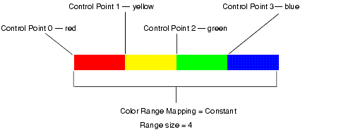
You set the color for each step by specifying the color of the control point at the low end of the step's range. In the example above,
- Control point 0 sets the color of the first (left-most) step
- Control point 1 sets the color of the second step
- Control point 2 sets the color of the third step
- Control point 3 sets the color of the fourth step
You could also define a constant mapping that assigns a single color value to all the data value in a range.
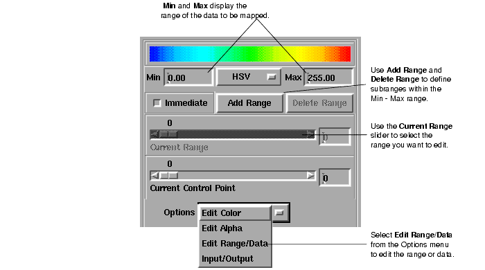
You use the following controls in the top portion of the Datamap editor panel to specify and edit the range of data you want to map.
In addition, you use these controls to specify whether you want your changes to be immediately visible in the view. If you set the Immediate button on, AVS/Express updates the view as you make changes. If you set Immediate off, AVS/Express does not update the view with your changes until you signal you are done by closing the Datamap Editor.
The Min and Max fields display the minimum and maximum data values in the current data set. You can create subranges within this range by using the Add Range button.
If you want to specify subranges within the range defined by Min and Max, click the Add Range button. The range added is after the last range. When you define more than one range, AVS/Express enables the Current Range slider in this panel. You use this slider to select the current range you want to edit.
To delete a range, select it in the Current Range slider and click Delete Range.
If you select Data from the Edit option menu, AVS/Express replaces the range sliders with Data Min and Data Max sliders:
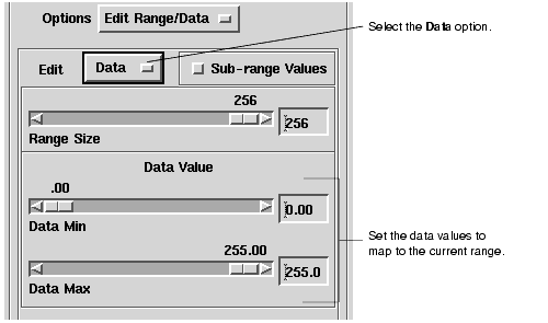
You use the Data Min and Data Max sliders to specify the data values to map to the current range. You can use these sliders to precisely control rendering by limiting the data values to be mapped to this subrange of the datamap.
AVS/Express clamps the data values for this subrange to the limits you define for Data Min and Data Max. If you define a datamap range that is smaller than the range of values in the data, AVS/Express sets data values below the minimum value to the minimum color value, and data values above the maximum value to the maximum color value.
The range you define using Min and Max does not need to cover the entire range of your data values. AVS/Express clamps the data values to the range or ranges you define. Specifically, if you define a datamap range that is smaller than the range of the data values, AVS/Express sets data values below the minimum value to the minimum color value, and data values above the maximum value to the maximum color value. If you have defined multiple data ranges, AVS/Express sets data values that fall between the ranges to the color of the minimum value of the range above.
To control the size of the currently selected datamap range or define a sub-range, select the range you want to edit in the Current Range slider and then choose Edit Range/Data from the Options menu. AVS/Express displays the following set of controls:
You use the Range size slider to specify the number of discrete steps AVS/Express uses to calculate colors for this range
- If you are defining a Linear color mapping, Range size is the number of discrete colors AVS/Express calculates when interpolating colors across the current datamap range.
- If you are defining a Constant mapping, Range size is the number of steps into which the data range is divided. You specify colors for each step by setting colors for the control points for each step.
If you select Sub-range Values, AVS/Express enables the two sliders, Range Min and Range Max. You can use these sliders to define the minimum and maximum values of sub-range currently selected in the Current Range slider above. You can define a separate size for the subrange within the datamap range to provide a more precise rendering over a portion of the data.
You use the following controls in the top portion of the Datamap editor panel to specify and edit the colors you want to map to the data.
To define the colors that AVS/Express uses to render data in the current range, you use this interface to:
By default, AVS/Express uses the HSV color model to specify color in the datamap editor. When you open the Datamap editor, the color model option menu is labeled HSV. It is located in the center of the panel, just below the datamap display.
To change color models, use the color model option menu to choose RGB. When you choose RGB, the sliders you use to set colors when you select the Edit Color option, set Red, Green, and Blue color values instead of Hue, Saturation, and Value.
- Note: When you change from HSV to RGB, AVS/Express does not convert the values to maintain the same colors in the new model. The current HSV values are interpreted as RGB values.When you switch color models you will need to redefine the control point colors.
To define the colors to map to the data values, you specify colors for "control points" in the data range. You choose the control point to set by selecting it on the Current Control Point slider. The number and location of the control points depends on whether you choose a Color Range Mapping option of Linear or Constant. You set this option on the Edit Color panel.
For Linear mappings, you define two points for each range. The lower control point specifies the color assigned to the minimum data values; the higher control point specifies the color assigned to the maximum data value. AVS/Express interpolates between these colors to generate a ramp of colors to assign to the data values in between. You can control the number of color values AVS/Express calculates by setting the Range Size.
For Constant mappings, one color value is assigned to each step in the range. You control the number of steps by setting Range Size. To set the color for each step in the data range, set the color for the control point associated with the step. The color is assigned to all the data values that fall within that step's range.
After you have selected the control point you want to edit, select Edit Color from the Options menu. AVS/Express displays the following editor panel:
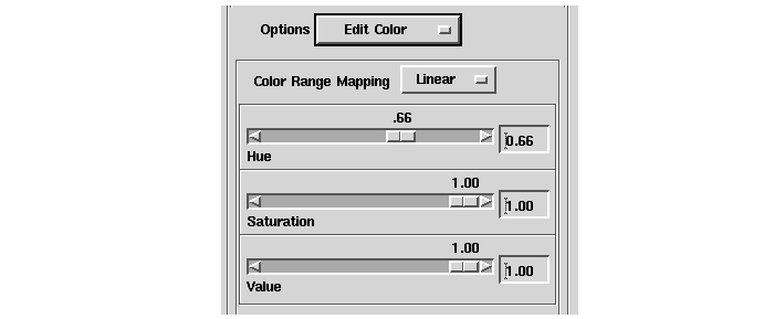
The Color Range Mapping editor panel for a Linear mapping displays a slider for each color component: Hue, Saturation, and Value; or Red, Green and Blue. You use these sliders to define the color you want to map to the currently selected control point in the current range. AVS/Express uses the color values you assign to the control points, and the number of steps you have specified in Range Size to interpolate a set of colors for the datamap and to assign them to the data values in the range.
The Color Range Mapping editor panel for a Constant mapping displays the same sliders. However, each step in the data range is assigned a single color, and you specify a color for each step by setting its control point. AVS/Express assigns this color to all the data values within that step in the currently selected range.You set the number of steps by setting Range Size.
To define an alpha mapping, select Edit Alpha from the Options menu. AVS/Express displays the following set of controls:
By default, the Datamap editor displays the controls for a Linear alpha mapping. To define a linear mapping of alpha values, use the slider to define the alpha value you want to associate with the current control point. Select another control point to define the range. AVS/Express uses these values to interpolate alpha values for the data range.
If you want to define a constant alpha value for the entire range, select Constant from the Alpha Range Mapping option menu.
To read the AVS/Express pre-defined datamaps or AVS5 *.cmap files, choose Input/Output from the Options menu. AVS/Express displays the following interface:
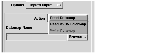
When you select Read Datamap from the Action option menu, AVS/Express displays the following dialog.
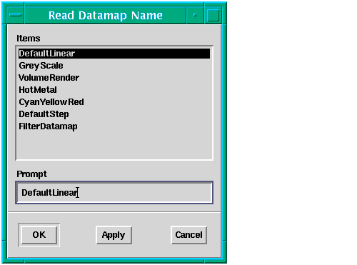
You use this dialog to select an AVS/Express default datamap by name. Select the name of the datamap you want to read, and click Apply to load the datamap and leave the dialog box open, or OK to read the datamap and close the dialog box.
All the default datamaps are defined in the HSV color model.
You can choose from the following datamaps:
- DefaultLinear - Contains a single data range of size 256 with two control points that run from blue to red, going through green.
- GreyScale - Contains a single data range of size 256 with two control points that run from black to white.
- VolumeRender - Contains two data ranges with a combined size of 256. The first range has an alpha value of 0 and the second has an alpha of 1. Taken together the two ranges run from blue to red through green - in the same manner as DefaultLinear.
- HotMetal - Contains three data ranges with a combined size of 256. It contains four control points that run from black to red to orange to white. Each data range has two control points. The middle data range shares control points with the ranges on either side. HotMetal is defined with an RGB color model.
- CyanYellowRed - Contains two data ranges with a combined size of 256. It contains three control points that run from cyan to yellow to red. Each data range has two control points. The middle control point is shared between the two data ranges. CyanYellowRed is defined with an RGB color model.
- DefaultStep -
- FilterDatamap -
Choose Read AVS5 Colormap from the Action option menu to read colormaps written in the AVS5 *.cmap format. AVS/Express displays a file browser that you can use to select the colormap file you want to read.
By default, the file browser opens to a default directory your AVS/Express installation directory containing a set of default *.cmap files. If you have stored colormap files in another location, you can use the file browser to navigate to them and select them by file name.
The Graph Editor is an interactive tool that you can use to edit the layout and data of graph objects connected to the 2D port of a UViewer or UViewer2D object.
- Setting the Graph Title
- Setting the Graph Properties
- Setting the Graph Style
- Specifying Axes
- Specifying Ticklines
- Specifying the Appearance of the Legend
- Specifying Contour Graph Characteristics
- Specifying Colors In The Graph Editor
The Graph option on the Editors menu is available when you are working in a view that includes a graph object. When you select Graph from the menu, AVS/Express displays the following interface:
Selecting an option from the Graph option menu displays the editor controls for those graph characteristics.
When you select Title from the Graph options menu, AVS/Express displays the following dialog box:
The title is a text string that appears above the graph. You can use this interface to
The Show Title button turns the display of the title on or off. When the button is selected (depressed), the title is displayed in the viewer window; when the button is not selected, the title is not displayed (the default).
You specify the title's text and appearance by selecting values for:
- Title - Enter the text for the graph title.
- Fill Color - The color used to fill the rectangular title area. You can supply either an X11 color name, a "#rrggbb" color format, or one of three special strings: background, antibackground or transparent. For more information about setting colors, see Specifying Colors In The Graph Editor on page 7-93
- Title Height - The height of the title's text. You supply a value that is a percentage of the width or height of the graph, whichever is smaller.
For example, if the X axis is 20 units long and the Y axis is 15 units long, specifying 2 for Title Height provides a line width of 3 units.
- Frame Width - Enables and sets a bounding box for the title area. A value of 0.00 (the default) turns the frame off. Use the Frame Width slider to turn the frame on and control the width of the line used to draw the box. Higher values of Frame Width produ.ce a thicker line.
- Title Font provides a scrolling window containing a list of the font choices for the title and other text in the graph. The following fonts are available:
courier
helvetica
helvetica-bold
roman-complex
roman-duplex
roman-italic
roman-simplex
script-complex
script-simplex
times-bold
Please note that font names are case insensitive and that spaces and dashes are ignored; for example, "roman-italic" is identical to "Roman Italic".
When you select Properties from the Graph options menu, AVS/Express displays the following interface:
- Select the current graph
- Set the drawing priority
- Select the graph type
- Set the appearance of the data points
if you have more than one graph object in the viewer, you use the Current Graph slider bar to specify which of the graphs in the viewer window is the current graph. The graphs are numbered in the order in which they are added to the view.
The current graph is the graph to which AVS/Express applies the changes you make in the Graph editor.
You use the Drawing Priority slider bar to set the drawing priority for a selected object in the graph. The default drawing priority for all objects in the graph is 0
All objects in a graph have a priority that determines the order in which they are drawn by the renderer. The DataViewer draws objects with higher priority last, so they appear in front of objects drawn in the same location. For example, if you select the Y ticklines and assign them a higher drawing priority than the data points in the graph, they will appear in front of the data points.
You use the Graph Type list to select the graph type for the current graph. You can choose from curve (the default), bar, barlines, scatter, area, staircase, or stairarea.
You specify the appearance of the data points in the graph by selecting values for the Color +, Color -, Baseline, and Legend fields.
You can use the Color +, Color -, and Baseline fields to mark a threshold in the data:
- Baseline is a value on the Y axis used as a boundary between Color + and Color-.
- Color+ is the color to apply to data points greater than Baseline; Color- is the color to apply to data points smaller than Baseline, Filled graphs (area and stair area) are also colored in this way. If you do not supply a value for Color -, the value of Color+ is applied to all of the data points.
- You can supply either an X11 color name, a "#rrggbb" color format, or one of three special strings: background, antibackground or transparent. For more information about setting colors, see Specifying Colors In The Graph Editor on page 7-93
- Legend is the text of a legend for the data points in the current graph. The legend that is created includes the Legend text as well as a key to the colors used for the data points.
When you select Style from the Graph options menu, AVS/Express displays the following interface:
You use this interface to specify the style characteristics of current graph. Only the characteristics that apply to the current graph's type are available. Characteristics that do not apply are grayed out.
You can set the following characteristics:
- Line Style - The style of line used to connect data points in the graph. You can choose from solid (the default), dashed, dotted, or dasheddotted (an alternating pattern of dashes and dots).
- Line Width - The width of the lines in a graph of type curve, staircase, or barline. You supply a value that is a percentage of the length of the graph's X or Y axis, whichever is shorter.
For example, if the X axis is 20 units long and the Y axis is 15 units long, specifying 2 for Line Width provides a line width of 3 units.
- Bar Width - The width of the bars in a graph of type bar. You supply a value that is a percentage of the distance between adjacent X values.
For example, if the distance between adjacent X values is 2 units, specifying 0,75 for Bar Width provides a bar width of 1.5 units.
- Bar Offset - A value that represents the center of a bar or barline in a graph of type "bar" or "barline". For example:
- Shift Position is a value that positions graphs of type staircase or stairarea by shifting the data points with respect to the X axis. For example:
You can select X Axis or Y Axis from the Graph option menu to change the layout and appearance of the graph axes. For example, selecting X Axis displays the following interface:
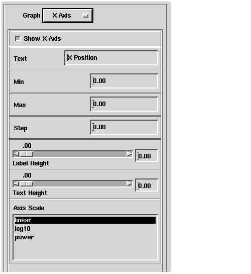
You use these interfaces to turn the display of the X and Y axes on and off and specify their appearance.
The Show X Axis and Show Y Axis buttons turn the display of the axes on or off. When the button is selected (depressed), the relevant axis is displayed; when the button is not selected, the axis is not displayed (the default).
Specifying the appearance of the axes includes specifying values both for their labels and their numbering systems.
The label for the X axis appears beneath the graph and the label for the Y axis appears to the left of the graph. You specify the text and appearance of a label by selecting values for the Text field, and the Label Height and Title Height slider bars.
- Text is the label's text.
- Label Height is the height of labels in the legend. You supply a value that is a percentage of the width or height of the rectangular label area, whichever is smaller.
- Title Height is the height of the legend's text. You supply a value that is a percentage of the width or height of the rectangular label area, whichever is smaller.
You specify the numerical characteristics of the axis by selecting values for the Min, Max, and Step fields, and in the Axis Scale window.
You can use these values to select a subset of the data as input for the axis. For example, you can narrow the range of 0-100 to 25-75 for a better examination of the data between these points.
- Step is the size of the increment used on the axis. If you turn on ticklines, they are positioned where the increments fall along the axis.
- Axis Scale specifies how the axis is scaled. You can choose linear (the default), log10, or power.
You can select X Ticklines or Y Ticklines to control the placement and appearance of axis ticklines. For example, selecting X Ticklines displays the following interface:
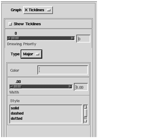
You use these interfaces to turn the display of X and Y ticklines on or off, specify the drawing priority and the appearance of the ticklines, and subdivide the axis into smaller increments.
There are two types of ticklines: major and minor.
- Major ticklines divide an axis into the increments specified with the Step parameter of the X-Axis and Y-axis interfaces.
- Minor ticklines subdivide the portion of an axis between major ticklines into smaller increments, whose size is determined by the Minor Tick Count slider of the X Ticklines and Y Ticklines interfaces (see Subdividing an axis into smaller increments on page 7-90).
When you turn the display of ticklines on or off, you add both types to, or remove both type from, an axis. You cannot choose to turn one type on or off but not the other.
The Show Ticklines buttons turn the display of ticklines on or off for the relevant axis. When the button is selected (depressed), the relevant ticklines are displayed; when the button is not selected, the ticklines are not displayed (the default).
You use the Drawing Priority slider bar to set the drawing priority for a selected object in the graph. The default drawing priority for all objects in the graph is 0.
All objects in a graph have a priority that determines the order in which they are drawn by the renderer. The DataViewer draws objects with higher priority last, so they appear in front of objects drawn in the same location. For example, if you select the Y ticklines and assign them a higher drawing priority than the data points in the graph, they will appear in front of the data points.
To specify the appearance of the ticklines, you use the Type option menu to select whether you want to edit the major or minor ticklines and then:
For information about specifying colors in the graph editor, see Specifying Colors In The Graph Editor on page 7-93.
- Use the Width slider bar to set the width of the minor ticklines.
- Use the Style scrolling list to select the style of line used to render the ticklines. You can choose solid (the default), dashed, dotted, or dasheddotted (an alternating pattern of dashes and dots).
An axis is divided into increments using the Step parameter of the X Axis and Y Axis interfaces (see Changing the appearance of the axes on page 7-88). As noted previously, major ticklines mark those increments. You can subdivide the portion of an axis between major ticklines into smaller increments by specifying a value greater than zero for the Minor Tick Count slider bar. The Graph editor adds the specified number of minor ticklines between each adjacent pair of major ticklines, spacing them evenly.
When you select Legend from the Graph option menu, AVS/Express displays the following interface:
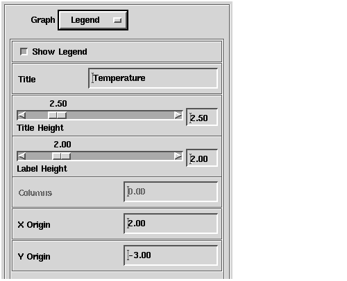
You use this interface to turn the display of a legend for the graph on or off and specify its appearance. Unlike the title for the graph, you specify the position of the legend.
The Show Legend button turns the display of the legend on or off. When the button is selected (depressed), the legend is displayed in the viewer window; when the button is not selected, the legend is not displayed (the default).
You specify the legend's text and appearance by selecting values for the Title, Columns, X Origin, and Y Origin fields; and the Title Height and Label Height slider bars.
- Title is the legend's text.
- Title Height is the height of the legend's text. You supply a value that is a percentage of the width or height of the rectangular title area, whichever is smaller.
- Label Height is the height of labels in the legend. You supply a value that is a percentage of the width or height of the rectangular legend area, whichever is smaller.
- Columns is the number of columns in the rectangular legend area.
- X Origin and Y Origin together specify the location of the lower-left corner of the rectangular legend area. You use these values to position the legend.
If you select Contour from the Graph option menu, AVS/Express displays the following interface:
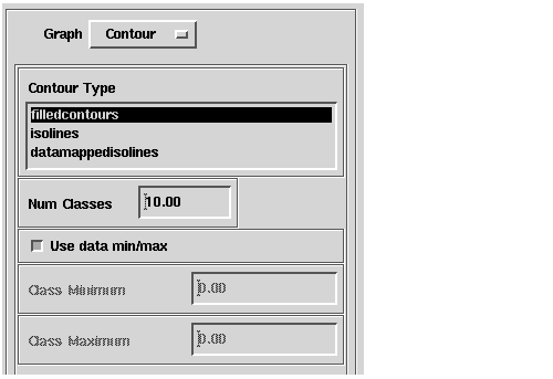
You use this interface to the specify the contour type, the number of classes of contours, and the range of data that each class represents.
- Contour Type - The style of isolines drawn in the graph. You can choose filled contours, isolines, and datamapped isolines. Filled contours and data mapped isolines are colored using the datamap color that corresponds to their data value.
- Num Classes - The number of isolines drawn in the graph.
- Use data min/max, Class Minimum, Class Maximum - You can use these three controls to position the isolines in the data. If the Use data min/max button is set the first class value is set to the minimum data value and the last class value is set to the maximum data value. If you set Use data min/max off, you can set Class Minimum and Class Maximum to specific data values. In this case the first class value is set to Class Minimum and the last class value is set to Class Maximum. The Num Classes field determines the number of isolines drawn between the minimum and maximum classes.
Many DataViewer editors include commands that require a color specification. You can specify the value as an X11 color name, "#rrggbb" color format, and three strings with special meaning.
In the "#rrggbb" format, rr, gg, and bb specify the hexadecimal representations of the values for the red, green, and blue color components, respectively. For example, "#ff0000" is red.
The special strings are as follows:
The following list shows the Xll color names. Please note that X11 names are case insensitive and that spaces are ignored; for example, "lightslateblue" is identical to "Light Slate Blue".
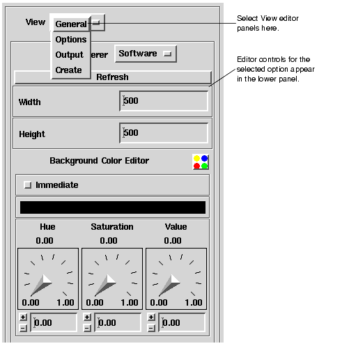
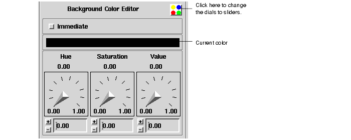
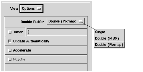
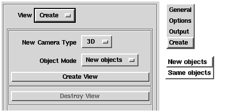
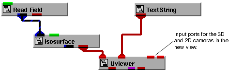
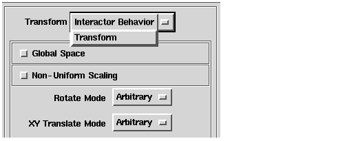
 Transform the current view object.
 Transform the current camera.
 Transform the current light.