This chapter presents a series of tutorials that provide fully worked examples of how to build applications with and use some of the Graphics Display Kit's most important features.
- Before you begin, Section 2.1
- Creating a view, Section 2.2
- Creating an object, Section 2.3
- Creating a view's window, Section 2.4
- Adding to a view's pull-down menus, Section 2.5
- Viewing multiple objects from one set of data, Section 2.6
- Creating an object hierarchy, Section 2.7
- Creating a custom transformation editor, Section 2.8
- Adding interactors to a view, Section 2.9
- Modifying a camera for annotation, Section 2.10
- Adding a second view window, Section 2.11
- Using accelerate mode in a view, Section 2.12
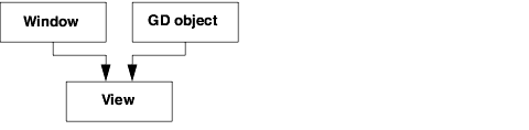
A Graphics Display Kit application consists of, at minimum, a view, a window in which to render the view, and one or more Graphics Display Kit (GD) objects:
Keep this picture in mind throughout the tutorials. A Graphics Display Kit application is not complete until it has at least these parts. An application can have other parts too, such as pull-down command lists and editors.
The Graphics Display Kit generally provides two ways to build each part (window, view, objects, etc.) of an application:
- From the ground up, by assembling low-level objects called base types.
- With an application component. An application component is a macro object that packages a set of Graphics Display Kit capabilities. For example, Mscene3D is a macro object that defines a view, including a 3D camera, a set of lights, and other view-related base-type objects.
When the goal of a tutorial is to focus on a particular part of an application, we build that part from the ground up, and build the other parts with application components.
In your applications, you typically do the same thing. You determine which parts of your application you can build with application components and which you need to assemble from the ground up. You can customize application components and construct your own.
The tutorial applications are available, in completed form, in Libraries.Examples.Graphics_Display.
Most of the objects in these tutorials are located in Libraries.Main and Libraries.Graphics_Display. The location of other objects is usually included in the text or accompanying diagrams. If you have trouble locating an object, you can use the Network Editor's object finder (Object->Find in All Libraries...).
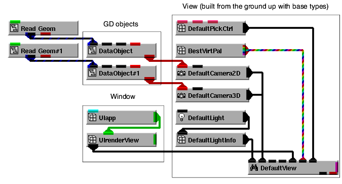
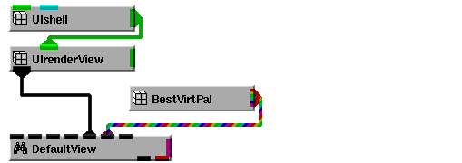
In this tutorial, we create a view from the ground up.
Here is what a view definition looks like, at the base-type level, along with the Graphics Display Kit objects and window that connect into the view:
1. Start AVS/Express and choose Application from the startup dialog, or if you have an existing AVS/Express session, start a new (Default)Application by selecting the appropriate entry from the File->New Application... dialog, or clear an existing Application workspace, as appropriate.
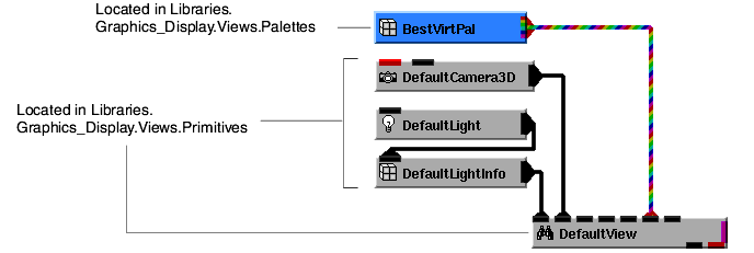
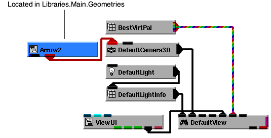
The view we'll build consists of DefaultView (the view's "root" object), DefaultCamera3D, DefaultLightOn, DefaultLightInfo, and BestVirtPal. These define, respectively, root information for the view, a camera, a light, basic lighting information (such as ambient lighting), and a virtual palette. Notice how a view can have its own virtual palette; multiple views can also share virtual palettes.
2. Instance into the DefaultApplication workspace the following objects: DefaultCamera3D, DefaultLightOn, DefaultLightInfo, DefaultView, and BestVirtPal. Then connect them as shown in the diagram below.
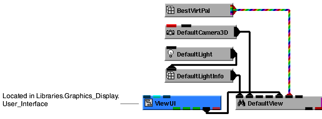
A Graphics Display Kit application requires a window in which to render the view. We create a window using the application component ViewUI. ViewUI defines a window, complete with a window panel and a UIrenderView panel in which the view appears.
Note that ViewUI can also be found in Full_Library.Components in the Graphics_Display collection. The easiest way to find an object in Full_Library is with the Find pop-up command.
When we instance ViewUI, an empty window appears. When we connect ViewUI to DefaultView, a black window appears inside the window. This is where the data is rendered.
Finally, we need to supply the Graphics Display Kit with an object to render. We can do this with Arrow2. It makes the data available both as a field (first output port) and as a Graphics Display Kit object (second output port), ready for rendering. We use the second output port.
The application renders an arrow in the view's window.
Notice that a Graphics Display Kit object connects to a camera (either DefaultCamera3D or DefaultCamera2D), which in turn connects to a view. You can connect several objects to a camera, and you can connect several 2D and 3D cameras to a view.
This completes the tutorial. The completed tutorial is available in Libraries.Examples.Graphics_Display.CreateView.
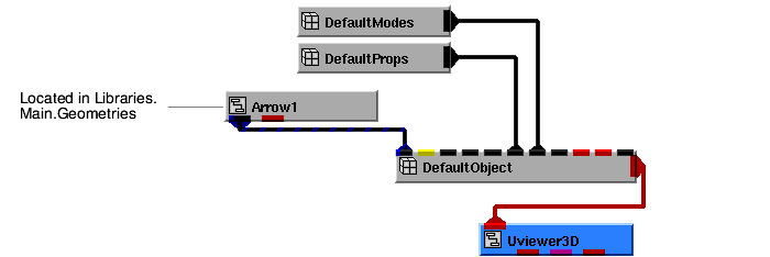
In this tutorial, we create a Graphics Display Kit object from the ground up.
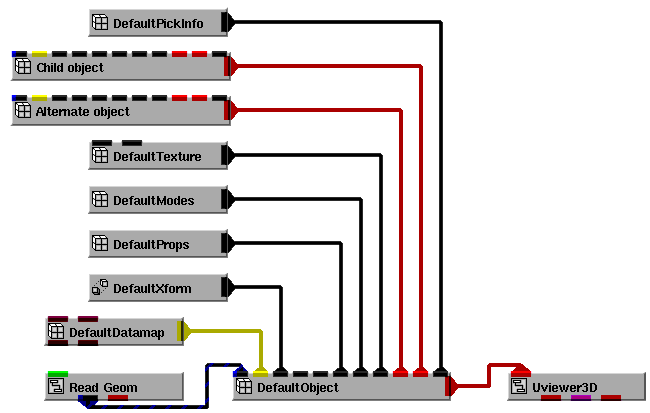
Here is what the definition of a Graphics Display Kit object looks like, at the base-type level. Most of the base types defining a Graphics Display Kit object are optional. In the diagram, the object is connected into Uviewer3D, a macro that defines a full-featured renderer, including a view and a rendering window.
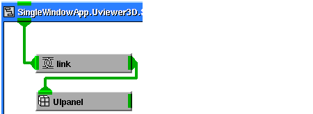
1. Start AVS/Express and choose Single-window DataViewer with no viewer (select None as the Viewer type) from the startup dialog, or, from an existing AVS/Express session, start a new Single-window DataViewer with no viewer by selecting the appropriate entries from the File->New Application... dialog, or clear an existing SingleWindowApp workspace, as appropriate.
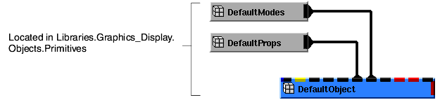
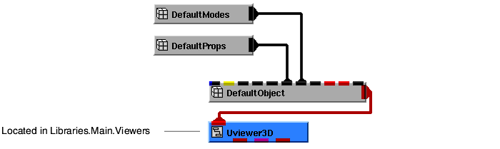
The data object we'll build consists of DefaultObject (the data object's "root" object), DefaultModes, and DefaultProps.
2. Instance into the SingleWindowApp workspace the following objects: DefaultModes, DefaultProps, and DefaultObject. Connect them as shown in the diagram below.
A Graphics Display Kit application requires a view for the Graphics Display Kit object and a window in which to render the view. For this tutorial, we create both with Uviewer3D. Uviewer3D is a full-featured 3D viewer, complete with a top-level object, a window, a view, and related editors.
When we instance Uviewer3D, a window with a black window inside it appears. This is where the data is rendered.
Finally, we need to supply the Graphics Display Kit with an object to render. We can do this with Arrow1. It makes the data available both as a field (first output port) and as a Graphics Display Kit object (second output port), ready for rendering. We use the second output port.
The application renders an arrow in the view's window.
This completes the tutorial. The completed tutorial is available in Libraries.Examples.Graphics_Display.CreateObject.
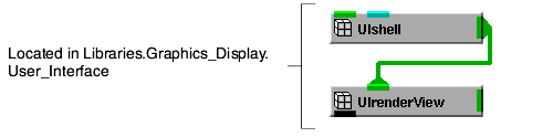
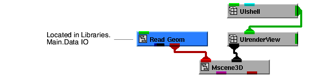
In this tutorial, we create a view's window.
Here is the minimum view window definition. In the diagram, the UIshell is connected to a UIrender View which is connected to the DefaultView, a view's root object.
1. Start AVS/Express and choose ModuleStack from the startup dialog, or if you have an existing AVS/Express session, start a new ModuleStack application by selecting the appropriate entry from the File->New Application... dialog, or clear an existing ModuleStack workspace, as appropriate.
A window for a Graphics Display Kit application consists of, at minimum, a UIshell object and a UIrenderView object. Both are defined in the User Interface Kit.
2. Instance into the ModuleStack workspace the objects UIshell and UIrenderView, then connect them as shown in the diagram below.
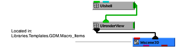
A Graphics Display Kit application requires a view. For this tutorial, we create the view using the application component Mscene3D. Mscene3D defines a 3D view, complete with root object, related base objects, and a top-level object.
When we connect UIrenderView to Mscene3D, a black window appears inside the window we created. This is where the data is rendered.
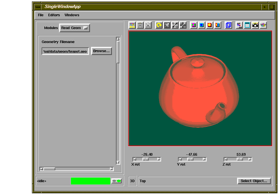
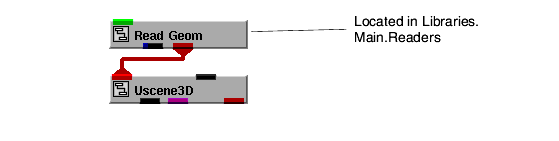
Finally, we need to create a Graphics Display Kit object with field data. We can create both with Read Geom, using the second output port.
5. We're now ready to specify a data file. In the ModuleStack window, select the Read Geom pull-down command. Select the Browse button. A dialog box appears. Select teapot.geo, then select the OK button.
The application renders the teapot in the view's window.
This completes the tutorial. The completed tutorial is available in Libraries.Examples.Graphics_Display.CreateViewUI.
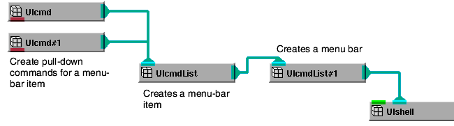
In this tutorial, we will add entries to the pull-down menu on the view's window.
Here is the basic structure of a command list. In the diagram, the command list is connected to UIshell, which defines the application's window:
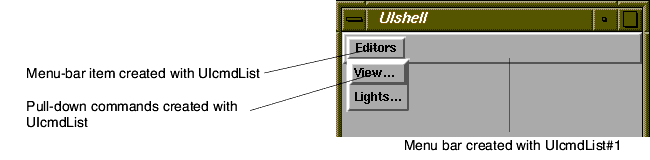
Here is an illustration of what the resulting menu bar might look like:
This is just one of many possible configurations. For example, you can connect multiple UIcmdList objects to the UIcmdList that creates the menu bar. This gives you a menu bar with multiple items on it. You can use other UI objects in addition to UIcmd. For example, another UIcmdList object creates a cascading pull-down menu. A UIoption object creates a pull-down command that works like an option box.
1. Start AVS/Express and choose Single-window DataViewer with no viewer (select None as the Viewer type) from the startup dialog, from an existing AVS/Express session, start a new Single-window DataViewer with no viewer by selecting the appropriate entries from the File->New Application... dialog, or clear an existing SingleWindowApp workspace, as appropriate.
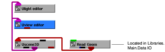
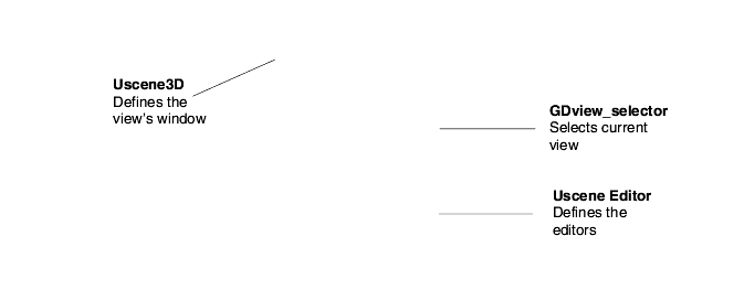
We create the application's window and view with the application component Uscene3D.
2. Instance into the SingleWindowApp workspace the object Uscene3D. Uscene3D can be found in Libraries.Accessories.Graphics.Modules.
When we instance Uscene3D, a black window appears inside the SingleWindowApp. This is where the data is rendered.
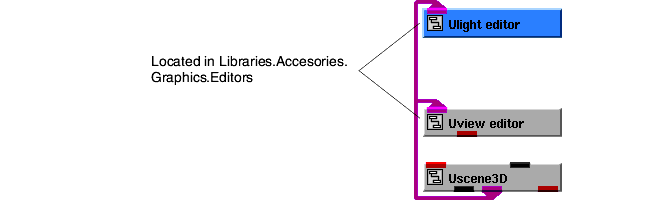
We want our application to have view and light editors that pop up when the user selects the appropriate pull-down command. For this tutorial, we create the editors using the application components Uview_editor and Ulight_editor. Each defines an edit object and a complete user interface (panel, sliders, buttons, etc.) for the editor. We will look at editors more closely in a later tutorial.
3. Instance Uview_editor and Ulight_editor, then connect them to the other objects, as shown in the diagram below. When the editors are instanced, the UIcmd contained in the editors is automatically installed on the Editors pull-down menu.
Notice that selecting a command displays its associated editor.
Finally, we need a Graphics Display Kit object with field data. We can create both with Read Geom, using the second output port.
6. We are now ready to specify a data file. In the SingleWindowApp window, select the Editors->Modules pull-down command. The user interface for Read_Geom will appear. Select thr browse button. A dialog box appears. Select teapot.geo, then select the OK button.
The application renders the teapot in the view's window.
The light editor is connected to the view, so, for example, when we turn the ambient light off, the view is updated accordingly.
This completes the tutorial. The completed tutorial is available in Libraries.Examples.Graphics_Display.CreateViewCmds.
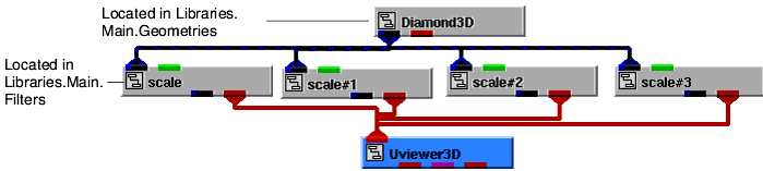
A view can include multiple Graphics Display Kit objects. In this tutorial, we create a view consisting of four objects, each derived from the same set of data.
1. Start AVS/Express and choose Single-window DataViewer with no viewer (select None as the Viewer type) from the startup dialog, from an existing AVS/Express session, start a new Single-window DataViewer with no viewer by selecting the appropriate entries from the File->New Application... dialog, or clear an existing SingleWindowApp workspace, as appropriate.
Uviewer3D is a full-featured 3D viewer, complete with a top-level object, a window, a view, and related editors. At the end of this tutorial, we explore the features of Uviewer3D.
Notice in Libraries.Main.Viewers:
- There are three different full-featured viewers, called Uviewer3D, Uviewer2D, and Uviewer. They differ in how they render Graphics Display Kit objects. Uviewer3D renders all objects in 3D. Uviewer2D renders all objects in 2D. Uviewer can do both; connect objects to be rendered in 3D to Uviewer's first input port, and objects to be rendered in 2D to its second input port.
We now create four Graphics Display Kit objects, each derived from the same set of data. We use Diamond3D to create the data to render, then four instances of the Data Visualization Kit's scale object to create the four objects.
3. Instance Diamond3D and scale (four copies), then connect them together and to UViewer3D, as shown in the diagram below.
The application renders the four objects. At first, though, it appears that only one object is present. This is because the four are overlapping.
b. With the Control key pressed, select the first object with the left mouse button. Release the control key.
5. Use Uviewer3D's capabilities to manipulate the objects. For example, here is a series of steps for testing the inheritance of properties:
c. Display the properties editor by selecting Editors->Object, then selecting Properties from the Object option menu.
d. In the properties editor, select Primary Color from the Object Color option menu. Use the dials to change the color. Notice that all objects change. By default, an object inherits the properties of its parent, so when we change the top-level object, all objects change.
e. In the object selector, select one of the other objects and select Apply. Now the properties editor shows that object's current properties. (You could also have selected the object itself using the mouse inside the view.)
f. In the properties editor, change the object's color. Notice that the color of that object changes.
6. Explore Uviewer3D's editors and mouse operations. The tables below summarize Uviewer3D's capabilities.
If you have a three-button mouse, some of the standard operations can also be performed using the middle mouse button.
This completes the tutorial. The completed tutorial is available in Libraries.Examples.Graphics_Display.MultipleObjs.
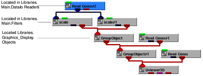
A Graphics Display Kit object can have zero or more child objects. You can connect multiple objects into a camera. These capabilities enable us to create elaborate object hierarchies. In this tutorial, we create a multi-level object hierarchy.
1. Start AVS/Express and choose Single-window DataViewer with no viewer (select None as the Viewer type) from the startup dialog, from an existing AVS/Express session, start a new Single-window DataViewer with no viewer by selecting the appropriate entries from the File->New Application... dialog, or clear an existing SingleWindowApp workspace, as appropriate.
3. Instance several objects, then connect them, as shown in the diagram below. After we have put the pieces together, we analyze what we have done.
The application creates the data object hierarchy shown below. Uviewer3D and the two instances of GroupObject create top-level objects that do not themselves have data:
Uviewer3D
GroupObject
GroupObject#1
scale (data from Diamond3D)
scale#1 (data from Diamond3D)
Read Geom #1
Read Geom
4. Display the modules window by selecting Editors->Modules. Select the first Read Geom from the option menu and press the Browse butto. A dialog box appears. Select dodec.geo, then select the OK button. Repeat the procedure for the other Read Geom entry in the option menu, but select a different file.
- the object created by Read Geom
- the object created by Read Geom#1
- the object created by scale
- the object created by scale#1.Notice that scale and scale#1 both use the data provided by Diamond3D.
6. Use Uviewer3D's capabilities to manipulate the objects. For example, using the object selector (Select Object...), select an object in the hierarchy. (Remember to select the Apply button when you select an object.) Point to an open area in the view and perform a translate operation. Different objects move, depending on which object in the hierarchy is selected.
This completes the tutorial. The completed tutorial is available in Libraries.Examples.Graphics_Display.ObjHierarchy.
Uviewer3D is a full-featured 3D viewer, complete with a top-level object, a window, a view, and related editors. In this tutorial, we add sliders to the bottom of Uviewer3D's window so the user can rotate the object.
1. Start AVS/Express and choose Single-window DataViewer with no viewer (select None as the Viewer type) from the startup dialog, from an existing AVS/Express session, start a new Single-window DataViewer with no viewer by selecting the appropriate entries from the File->New Application... dialog, or clear an existing SingleWindowApp workspace, as appropriate.
3. Display the modules window by selecting Editors->Modules. Select the Browse button from the Read Geom user interface. A dialog box appears. Select teapot.geo, then select the OK button.
We now customize Uviewer3D. We start by resizing the view's rendering panel to create space at the bottom of the window for the sliders. AVS/Express' active execution model enables us to see the results of our changes as we make them.
The figure below shows what Uviewer3D looks like. The annotations indicate the class name and purpose of most of Uviewer3D's objects:
Scene defines the view's window. This is the object we want to modify.
a. Open Scene in DisplayParameters mode. Open View in DisplayParameters mode. Open ViewUI in DisplayParameters mode. Open ViewPanel in DisplayParameters mode.
b. Export the output port on panel. To export the output port on the panel subobject, open its properties editor. Set Property Group to All Properties. Click NE port levels and change {0,0} to {0,6}. Click Set.
a. Open Scene in Display Parameters mode. Open View in Display Parameters mode. Open ViewUI in Display Parameters mode. Open ViewFrame in DisplayParameters mode. Open the height subobject to see height's value expression.
Notice that the view window's rendering panel is now shorter, leaving room at the bottom for a set of sliders.
We are now back to Uviewer3D's maximized window.
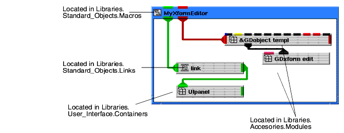
We now create a transform editor inside of Uviewer3D, which appears to the user as a set of three sliders at the bottom of the view's window.
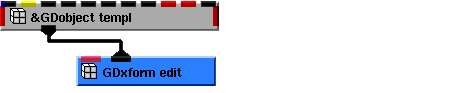
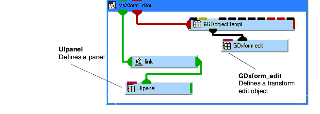
d. Instance link located in Libraries.Standard_Objects.Links, UIpanel located in Libraries.User_Interface.Containers, GDObject_templ located in Libraries.Accessories.Graphics.Modules, and GDxform_edit located in Libraries.Accessories.Graphics.Modules.
e. Export the link so it is an input port on MyXformEditor and connect link and UIpanel as shown in the following diagram.
f. Modify UIpanel by setting its y subobject to 415 and its width subobject to =>link.clientWidth. This positions the panel just below the view window and makes the panel the same width as the view window.
g. Change GDobject_templ to a reference by setting its ref_mode property to '&' using the Properties Editor. Export GDobject_templ so it is an input port on MyXformEditor. The input port can be selected using the Object Editor of the GDobject_templ. You may have to toggle the Display Input Port checkbox.
h. Open GDobject_templ and export its xform subobject so it is an output port on GDobject_templ. To get the output port of an xform subobject, open its Properties Editor. Set Property Group to All Properties. Click on NE port levels and change {2,0} to {2,2} and click Set. Connect GDobject_templ and GDxform_edit as shown in the diagram below.
At this stage, MyXformEditor should appear as illustrated in the following figure.
k. Connect the right input port of MyXformEditor to in_view.picked_obj. This provides MyXformEditor with an object to transform.
l. Export MyXformEditor.link so it is an output port on Scene_Editor. To get the output port on the link, open its Properties Editor. Set Property Group to All Properties. Click NEportLevels and change {2,1} to {3,1} and click Set.
n. Connect the right output port of Scene to the right input port of Scene Editor. This provides MyXformEditor's panel a parent window for the three sliders that will be added.
Take a closer look at MyXformEditor.
The figure below shows what MyXformEditor looks like. The annotations indicate the class name and purpose of two of MyXformEditor's objects (the other two objects are references for the macro):
Although MyXformEditor so far defines just the skeleton of a fully functional editor, it does illustrate the two main components of an editor:
- An edit object - Most base objects-DefaultView, DefaultCamera3D, DefaultModes, and so forth-have companion edit objects-GDview_edit, GDcamera_edit, GDmodes_edit, and so forth. You will see how these work as we go along.
- A user interface - The user interface consists of UI widget objects, like panels, sliders, buttons, and entry fields. Many of the widgets are connected to subobjects of the edit object.
Here is how an editor works: the user modifies a UI widget that's connected to an edit object; the edit object in turn updates the base object to which it is connected.
We now create three user-interface sliders inside MyXformEditor.
Notice that a slider appears in the viewing window.
Notice that the slider changes accordingly.
The next step is to connect the sliders to GDxform_edit.
b. If x_rot does not already have an output port, create one with the Add Output Port pop-up command.
c. Export x_rot's output port with the Export Port pop-up command. Remember that you must position the mouse pointer over the port when selecting the pop-up command.
Here is what GDxform_edit should look like, both opened and closed:
7. Connect the three UIsliders to GDxform_edit, as shown in the followoung diagram. Note that objects in the diagram have been shifted to make the connection lines clearer.
The last step is to configure the transform editor so it executes properly.
This causes the Xrot, Yrot and Zrot subobjects to be updated when the xform subobject changes. This happens when an object in the view is transformed using the mouse. The Graphics Display Kit editors typically do not update the subobjects that are normally connected to UI widgets unless shell_vis is set to 1.
This causes the transform editor to work in absolute mode instead of relative mode. This subobject must be set to either 0 or 1 for the editor to work properly.
This completes the tutorial. The completed tutorial is available in Libraries.Examples.Graphics_Display.CustomEdit.
Note that at this point, you could rename Uviewer3D and save it back into Libraries, thereby creating a customized viewer.
Interactors along with the Graphics Display Kit's virtual trackball editor allow you to directly manipulate objects in the view window. In this tutorial, we add an interactor to a view and demonstrate some of the capabilities of the virtual trackball editor.
1. Start AVS/Express and choose Single-window DataViewer with no viewer (select None as the Viewer type) from the startup dialog, from an existing AVS/Express session, start a new Single-window DataViewer with no viewer by selecting the appropriate entries from the File->New Application... dialog, or clear an existing SingleWindowApp workspace, as appropriate.
We create the application's window and view with the application component Uscene3D.
When we instance Uscene3D, a black window appears inside it. This is where the data is rendered.
We need a Graphics Display Kit object with field data. We can create both with Read Geom, using the second output port.
4. We are now ready to specify a data file. Select Editors->Modules to display the Read Geom user interface. Press the Browse button. A dialog box appears. Select teapot.geo, then select the OK button.
The application renders the teapot in the view's window.
We need to provide access to some of the parameters kept inside the view.
We need to have a UI interactor and the virtual trackball editor.
1. Instance UItwoPoint and GDtrack_edit and connect them (exposing ports as necessary) as shown in the diagram that follows.
a. Connect Uview_link.render_view to UItwoPoint.view. This provides the interactor with the window in which to look for the mouse gesture.
b. Connect UItwoPoint.x to GDtrack_edit.x. Connect UItwoPoint.y to GDtrack_edit.y. Connect UItwoPoint.state to GDtrack_edit.event. These provide the trackball editor with screen space XY positions and the events start, run or stop.
c. Connect UItwoPoint.time to GDtrack_edit.time. This provides the trackball editor with the time of the event. This is used to determine if track rolling should be enabled.
d. Connect Uview_link to GDtrack_edit.view. Connect Uview_link.picked_camera to GDtrack_edit.camera. Connect Uview_link.picked_obj to GDtrack_edit.obj. These provide the trackball editor with an object to edit as well as the view and camera which are needed to convert screen space XY positions into a transformation matrix.
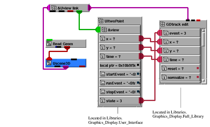
Note that the port correspondence can be found by using the 'info' option (right mouse click) on Uview_link and GDtrack_edit objects.
With these connections made, the trackball editor should now produce a transformation matrix that causes rotation when the left mouse button is held down and dragged. This is the default for the trackball editor.
Now that we have the interactor and the trackball editor working the view window, let's explore the capabilities of the editor.
The mode subobject in GDtrack_edit controls what type of transformation the editor performs. With the connections you have made, you can control the mode by using the Left Button option menu at the bottom of the view. By default, the value of mode should be 0 which means Rotate. The following values are valid:
The rot_mode subobject controls what if any constraints are applied to the rotation. The following values are valid:
This illustrates that one instance of the GDtrack_edit module can be used to perform all possible interactions with the object. This is done by simply selecting the type of interaction you want to perform prior to making the apppropriate gesture with the mouse.
The scale_mode subobject controls what if any constraints are applied to scaling. The following values are valid:
The xlate_mode subobject controls what if any constraints are applied to XY translation. The following values are valid:
This completes the tutorial. The completed tutorial is available in Libraries.Examples.Graphics_Display.AddInteractors.
Many times you might like to add non-transformable annotation or simple graphics to a view. This example illustrates one way to do this by having a non-pickable 2D camera in the view and placing the annotation or simple graphics in that camera.
1. Start AVS/Express and choose Single-window DataViewer with no viewer (select None as the Viewer type) from the startup dialog, from an existing AVS/Express session, start a new Single-window DataViewer with no viewer by selecting the appropriate entries from the File->New Application... dialog, or clear an existing SingleWindowApp workspace, as appropriate.
We need to create a Graphics Display Kit object.
4. We're now ready to specify a data file. Select Editors->Modules to display the Read Geom user interface. Select the Browse button. A dialog box appears. Select teapot.geo, then select the OK button.
The application renders the teapot in the view's window.
We need to modify the 2D camera so annotation and simple graphics will be non-transformable.
This makes the camera as well as all the objects in the camera unpickable. You will be unable to directly manipulate the objects, making them effectively "non-transformable". Note however, that if the transform subobject of the object changes in some other manner, the object will still be transformed.
We can now add some text and graphics that we want to be non-transformable to the view.
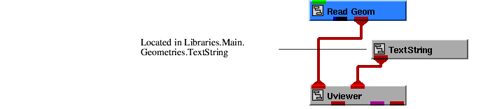
The text string "Hello World" will be rendered in the middle of the view. We need to move it to the top of the view, render a different string and make the font larger.
c. Scroll down to find the position subobject and open it. This position represent the XY coordinates where the string will be rendered.
d. Replace the current values with -4.0 for X and 3.5 for Y. With the current string and font size, "Hello World" is rendered towards the upper left.
a. Select Editors->Modules to display the modules window. Select TextString from the Modules option menu. The user interface for TextString appears.
We now have a title at the top of the view that is non-transformable.
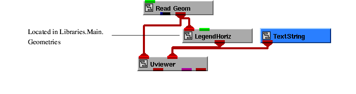
We can now add a legend to the view that will also be non-transformable.
Notice that the only objects that you can pick are Top3D and teapot. Since the text string and legend are in a camera that is not pickable, they cannot be selected.
This completes the tutorial. The completed tutorial is available in Libraries.Examples.Graphics_Display.AnnoCamera.
Many times in an application you may want to have more than one view window in a single user interface shell. In this tutorial, we add a second view window to an existing viewer and share all the editors among the two views.
1. Start AVS/Express and choose Multi-window DataViewer with no viewer (select None as the Viewer type) from the startup dialog, from an existing AVS/Express session, start a new Multi-window DataViewer with no viewer by selecting the appropriate entries from the File->New Application... dialog, or clear an existing MultiWindowApp workspace, as appropriate.
We need to add the second view window to Uviewer3D and configure the viewer so all the editors are shared between the views.
4. Modify the existing view so it occupies the left hand side of the view window. Make sure to keep the behavior of the view resizing when the panel resizes.
a. Open Scene in DisplayParameters mode. Open View in DisplayParameters mode. Open ViewUI in DisplayParameters mode. Open ViewFrame.
d. Export the output port of panel by opening its Properties Editor. Set Property Group to All Properties. Click on NEportLevels and change {0,0} to {0,6} and click Set..
5. Create a second view and modify it to occupy the right hand side of the view window. Make sure to keep the behavior of the view resizing when the panel resizes.
a. Instance Uscene3D (from Libraries.Accesories.Graphics) into UViewer3D (which should still be maximized).
b. Open UScene3D in DisplayParameters mode. Open View in DisplayParameters mode. Open ViewUI in DisplayParameters mode.
c. Delete ViewPanel. We are reparenting the view to the existing window provided by Uviewer3D, so we need to delete this scene's original parent.
d. Open ViewFrame in DisplayParameters mode. Export the input port of parent. To export output port on parent, open its Properties Editor and set Property Group to All Properties. Click on NEportLevels and change {0,0} to {0,5} and click Set.
e. Reparent the second view by connecting the right output port of Scene (exposed in Step 4) to the newly exposed right input port of Uscene3D.
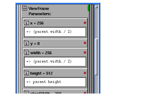
f. Set up the second view's geometry as explained below. Set x to be a reference to (parent.width / 2) . Set width to be a reference to (parent.width / 2). Set height to be a reference to parent.height. When set, the new values should appear as in the following diagram:
This causes the second view to occupy the right hand side of the shell. This also causes the view to resize when its parent resizes.
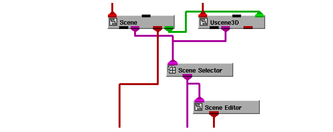
6. Share the viewer's editors between the two views by connecting Uscene3D.View.View to Scene_Selector.input_views.
The diagram below shows the final connections between Scene, Uscene3D and Scene_Selector inside Uviewer3D.
We need to create Graphics Display Kit objects and provide them with data to render.
12. We're now ready to specify a data file. Select Editors->Modules to display the user interface for the Read Geom module appear. Select the Browse button to make a dialog box appear. Select teapot.geo, then select the OK button.
The application renders the teapot in the left view window.
13. We're now ready to specify a data file. Select Read_Geom#1 from the Modules option menu to make the user interface for the other Read Geom module appear. Select the Browse button to make a dialog box appears. Select math.geo, then select the OK button.
The application renders math in the right view window.
We can now share the editors between the two views. Any interaction in either view makes that view current and switches the editors to work with the objects in that view.
14. Select the teapot in the left view window with the left mouse button. Notice that the Current Object at the bottom of the view window says teapot.
15. Notice that the virtual trackball editor works in the left view window. The normal gestures for rotation, scale, and translation apply.
17. Select math in the right view window with the left mouse button. Notice that the Current Object at the bottom of the view window says math.
19. Select Editors->Object. The object editor dialog box appears. Select the Reset icon. Select the Normalize icon. Select the Center icon. Notice that these operations effect only the math object.
This completes the tutorial. The completed tutorial is available in Libraries.Examples.Graphics_Display.TwoView.
Rendering performance can be an issue when working with complex data sets, particularly when you need to move another smaller graphical object over or through such a data set (for example, when probing a large geometry).
In such cases you may want to take advantage of accelerate mode rendering in which objects in a view are marked as either dynamic or static and then handled differently by the renderer(s):
- Small objects that will need to be moved should be marked as dynamic.
- Large data sets should marked as static (the default). Image and z-buffer information for static object is stored by the renderer(s).
When dynamic objects are subsequently moved, only they require rerendering - into the buffers that already contain the rendered static objects. Note that if static objects are moved, they must obviously be also rerendered thus negating the performance advantages of accelerate mode.
Note: The performance of accelerate mode in renderers is highly dependent on the technique that the graphics library/hardware vendor uses for grabbing frame and Z buffers, and does not therefore always provide a significant performance advantage. For example, accelerate mode is not noticably faster on a PC than normal rendering (and in fact is slower on some machines).
In the following tutorial, you will move a simple 2D arrow glyph (the dynamic object) over a large 3D geometry (the static object) with accelerate mode active and inactive to compare performance in both states.
Note: In this example, because the only dynamic object is 2D, only the image buffer need be rerendered into the buffer containing the static object - the Z-buffer need not be saved.
In order to perform the manipulation of the graphic objects required to complete this tutorial, you will need to use some of the basic mouse operations that control editing in the Uviewer scene window:
1. Start AVS/Express and choose None from the startup dialog, or if you have an existing AVS/Express session, delete or close any existing application workspaces that you have open.
The Accel2DGlyph macro contains a complete example network complete with large and small data sets and a viewer already set up for accelerate mode.
2. Instance into the empty NE workspace the object Accel2DGlyph from the Graphics Display Examples library.
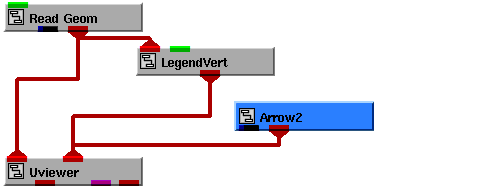
The DataViewer instanced as part of the Accel2DGlyph network contains a 3D map of the Caribbean ($XP_ROOT/data/geoms/carib.geo, read in via the Read_Field module), and an instance of a simple 2D arrow (Templates.GEOMS.Arrow2). (There is also a legend for the map, but this is can be ignored for the purposes of this tutorial.)
4. Accelerate mode is controlled at the low level by the accel parameter of the DefaultView object. However, the Single Window Dataviewer used in this tutorial provides much easier access to this parameter via the Accelerate toggle button in the View Editor that forms part of it's user interface.
To look at the Accelerate control, open the View Editor by selecting Editors->View from the Dataviewer menubar and then selecting Options from the View popup at the top of the Module Panel. You will see that the Accelerate toggle button is set on, and that accelerate mode is therefore active. Later on we'll turn accelerate mode off and see the impact that this has on rendering performance.
5. The nature (dynamic or static) of an object in a view is controlled at the low level by the type parameter set on objects. However, the Viewer used in this tutorial provides much easier access to this parameter via the Dynamic toggle button in the Object Editor that forms part of it's user interface. To see the setting of Dynamic control for the Arrow2 and carib objects:
b. Select the Arrow2 object by placing the cursor over it and control-left-clicking (when selected, "Arrow2" will replace "Top3D" on the message line below the view). You will see that the Dynamic toggle button is set on, marking the arrow as a dynamic object for accelerate mode rendering.
c. Select the carib object by placing the cursor over it and control-left-clicking (when selected, "carib" will replace "Arrow2" on the message line below the view). You will see that the Dynamic toggle button is set off, marking the carib as a static object for accelerate mode rendering.
7. Translate Arrow2D over carib by moving the mouse while holding the Control key and the middle mouse button. Note the speed at which the arrow is rerendered with accelerate mode on.
8. To compare rendering performance with accelerate mode off, unset the Accelerate toggle on the View Editor and then repeat step 7. You should notice a significant decrease in performance.
9. You can obtain a more quantitative measure of the difference performance with the Timer facility (also set via a toggle button in the Options page on the View Editor), which reports rendering performance in Frames Per Second (FPS) in the VCP window, set on:
b. "Throw" the arrow object with accelerate mode on (by dragging the mouse with the middle button held down and realeasing the button while the mouse is still in motion). To stop rotation, left-click in the view, at which time the rendering speed will be written to the VCP.
c. Repeat the operation outlined in step b. above with accelerate mode off. The rendering speed reported by the timer should be significantly lower.
For more examples of the use of accelerate mode, see related examples available in the Examples.Graphics_Display library.
|
|
Copyright © 2001 Advanced Visual Systems
Inc.
All rights reserved.