4
Geometries
This chapter provides reference pages for each of the geometries in the Data Visualization Kit.
Geometries are macros that create simple geometric objects (lines, planes, diamonds, arrows, crosshairs, etc.) as unstructured Meshes. You can use these simple geometries in two basic ways:
When used with the glyph macro, a copy of the geometry will be drawn at each node in the mesh. The copies can be colored and scaled according to the data values at that node location. In some sense, this visualization technique is the closest representation of a field to reality-it shows data only at the nodes where it actually exists; no interpolation is done that "fills in" data between the real node locations.
In advector, the geometry becomes the representation of the particles that are being advected.
- As input to one of the macros that require a sampling object such as probe, slice, interp data, streamlines, or cut. In this case, the geometry becomes the sampling object.
In probe, streamlines, and interp data, the geometry is a pointer that you move around the field, sampling the data it is pointing to or intersects.
In slice and cut, the geometry is a slicing object that either divides a field in two, or extracts the data where the slicing object intersects the field.
Geometries can be 1, 2, or 3D objects (a point, a line, a box). Geometries can be specialized according to the type of mesh you are intending to sample with them. The "F" prefix geometries take a field as input, tailoring their output to the extents of this input field. For example, FLine2D assumes a 2D input field, while FLine3D assumes a 3D input field. Other geometries do not take inputs (Line2D, Line3D).
Lastly, some geometries come with their own Transformation Panel user interface that lets you move them around in space, while others require that you use the data viewer's transformation facilities. In this latter case, to move the geometry you select the geometry as the current object, then transform it with the mouse buttons or the viewer's object transformation panel.
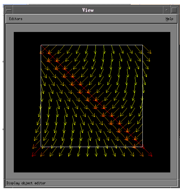
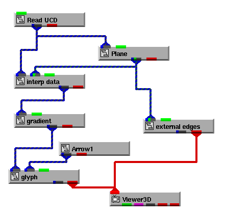
Here is one sample network (Libraries.Examples.Vizualization.Grad) that shows both basic functions of geometries-drawing a glyph at node points and creating a sampling object-used at once. The network creates a picture of the vector gradient in a field. In this example:
- The Arrow1 geometry is creating the arrows. They are sent to glyph, which produces a copy of the arrow at each node in the input field. glyph's vector parameter is turned on, so the arrows are rotated to reflect the vector at each node.
- The Plane (actually FPlane) geometry is creating a sampling plane, subsetting the input field so that vectors are drawn only for nodes on the sampling plane, not for the entire field.
And here is the resulting output:
Note that Arrow1 could be replaced with any number of geometries (Arrow2, Axis3D, Cross3D, Diamond3D). The only difference is that you would see that geometry instead of the wireframe arrows. FPlane could be replaced with FPoint3D, FLine3D, or FBox. Then, instead of a slice plane of vectors, you would see respectively, a single point vector, all vectors along a line, or all vectors within the volume of a box.
The Geometries are located in these paths in the Network Editor:
Libraries.Main.Geometries
Libraries.Visualization.Geometries
Libraries.Templates.GEOMS
|
|
Copyright © 2001 Advanced Visual Systems
Inc.
All rights reserved.